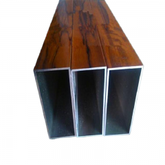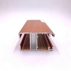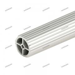
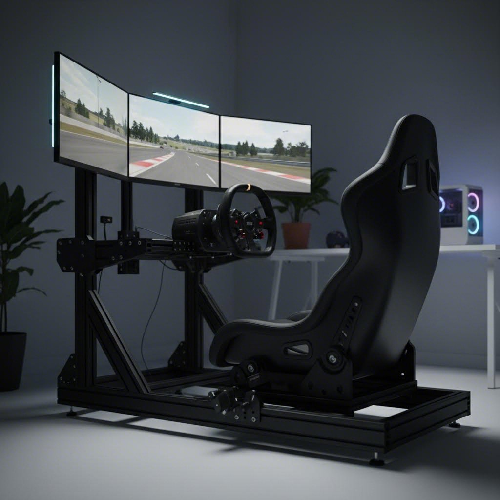
Have you ever felt your desk vibrate under the stress of force feedback, or noticed your wheel stand flexing during hard braking? If you're ready to leave those frustrations behind, you're likely eyeing an aluminum extrusion sim racing rig as your next upgrade. These modular cockpits have become the gold standard for serious sim racers, and for good reason.
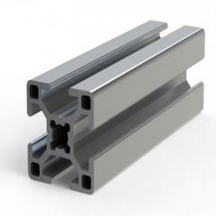
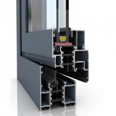
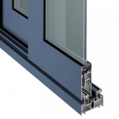
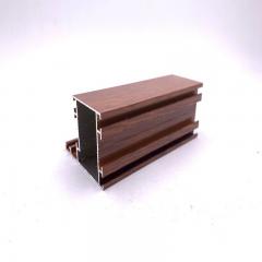
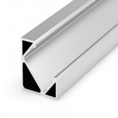
An aluminum extrusion sim rig uses industrial-grade T-slot aluminum profiles as its structural foundation. Unlike traditional welded steel frames or molded plastic cockpits, these systems are designed around interlocking aluminum strips that bolt together with incredible precision. The result? A rock-solid platform that eliminates virtually all flex and vibration, even when paired with powerful direct drive wheel bases pushing 20Nm or more of torque.
If you're transitioning from entry-level setups like Playseat or basic GT Omega rigs, you'll immediately notice the difference in rigidity. Entry-level cockpits often struggle to contain the forces generated by modern racing wheels and load cell pedals. An aluminum sim racing rig, however, provides a foundation that stays planted no matter how aggressive your driving style becomes.
The true benefit extends beyond just rigidity. These rigs offer unmatched customization potential. Every piece of aluminum profile features slot gaps along its length, allowing you to mount equipment at virtually any position. Want to add a shifter mount, keyboard tray, or triple monitor stand? You can bolt accessories anywhere along the profile where they'll fit. This flexibility is something traditional rig metal sim cockpit designs simply cannot match.
Consider this: when your sim rig flexes, it introduces movement that interferes with the force feedback your wheel base produces. This waters down the tactile information you rely on for precision driving. An 8020 sim rig eliminates this problem entirely, delivering every nuance of feedback directly to your hands.
You'll often hear these cockpits called "8020 rigs" or "80/20 rigs." This naming convention traditionally refers to the 80x20mm profile dimensions that were commonly used in early builds. However, as the 80/20 Inc. naming guide explains, modern sim rigs actually use a variety of profile sizes, including 40x40mm, 40x80mm, 40x120mm, and even 40x160mm strips.
The T-slot profile naming convention typically follows this pattern:
The sturdiest aluminum extrusion sim rig builds, such as premium offerings from established manufacturers, use larger 40x160mm profiles in critical areas to ensure zero flex during intense racing sessions. Budget-friendly options might rely on 40x80mm profiles, which still outperform most tubular or all-in-one alternatives.
What separates these systems from welded steel or molded plastic alternatives is their modular nature. Steel rigs can be incredibly rigid, but they're permanent structures with limited adjustment options. Plastic cockpits offer portability but sacrifice the rigidity needed for high-performance equipment. An 8020 rig gives you the best of both worlds: industrial strength combined with the ability to reconfigure, expand, or completely redesign your setup as your sim racing journey evolves.
Throughout this guide, we'll explore everything you need to know about building or buying your ideal aluminum profile cockpit, from selecting the right profile sizes and materials to planning your ergonomic layout and sourcing quality components. Whether you're a complete DIY enthusiast or prefer purchasing a pre-designed kit, you'll find manufacturer-agnostic guidance focused on helping you make informed decisions rather than pushing specific brands.
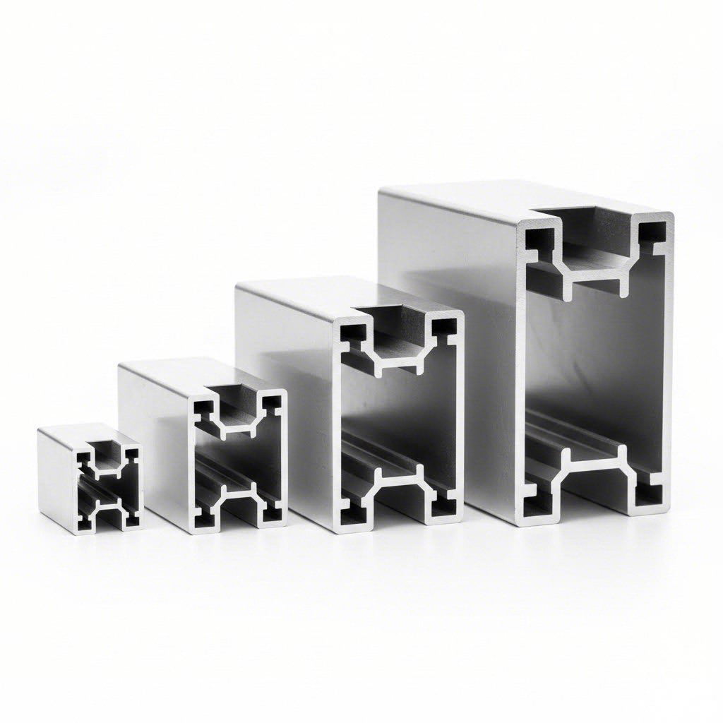
Choosing the right 8020 profile for your sim racing build isn't just about picking the biggest option available. It's about matching structural strength to your specific equipment and driving style. Sounds complex? Don't worry. Once you understand how profile sizes relate to load capacity and torque handling, selecting the perfect aluminum profile sim rig components becomes straightforward.
Aluminum extrusion profiles are measured by their cross-sectional dimensions in millimeters. A 2020 profile measures 20mm x 20mm, while a 4040 profile measures 40mm x 40mm. These seemingly small differences translate to significant variations in rigidity, load-bearing capacity, and overall performance under stress.
Not all parts of your rig experience the same forces. Your pedal deck handles heavy braking loads pushing directly into the frame. Your wheel mount absorbs rotational torque from force feedback. Your main frame ties everything together while supporting your body weight. Each application benefits from specific profile sizes.
| Profile Size | Dimensions | Typical Load Capacity | Recommended Use Cases | Wheel Base Compatibility |
|---|---|---|---|---|
| 2020 | 20mm x 20mm | Light loads only | Accessory mounts, cable management, keyboard trays | Not recommended for wheel mounting |
| 4040 | 40mm x 40mm | Moderate loads | Secondary frame supports, monitor mounts, shifter brackets | Belt-driven bases up to 8Nm |
| 40x80 | 40mm x 80mm | Heavy loads | Pedal decks, wheel mounts, main frame rails | Direct drive bases up to 15Nm |
| 80x80 | 80mm x 80mm | Extreme loads | Main frame uprights, high-torque wheel mounts, pedal deck bases | High-end direct drive 20Nm+ |
According to machining industry specifications, the 8020 profile offers the highest structural integrity among common extrusion sizes, with significantly thicker walls that resist bending and twisting under heavy loads. This makes it the preferred choice for alu profile sim rig builds designed around powerful direct drive wheel bases.
You'll encounter different series classifications when shopping for extrusions. These categories organize profiles by their general size range and slot compatibility:
For sim racing, the 40 Series dominates most builds due to its ideal balance of strength, weight, and accessory compatibility. The 8mm slot width accommodates a wide range of T-nuts and mounting hardware available from multiple manufacturers.
Why do heavier direct drive wheel bases require larger profiles? Imagine this scenario: you're running a Simucube 2 Pro pushing 25Nm of peak torque through a quick direction change. That rotational force transfers directly into your wheel mount and frame. Undersized profiles will flex, absorbing energy that should reach your hands as tactile feedback.
Belt-driven wheel bases like entry-level Logitech or Thrustmaster units typically produce 3-5Nm of torque. A well-constructed 4040 aluminum profile sim rig handles these forces comfortably. However, stepping up to mid-range direct drive options like the Fanatec DD or Moza R9 introduces 8-12Nm loads that benefit from 40x80 profiles in critical mounting areas.
High-end direct drive bases from Simucube, Asetek, or Fanatec's DD1/DD2 lineup generate 15-25Nm or more. These powerhouses demand 80x80 profiles for wheel mounting and main frame uprights. The larger cross-section and thicker walls provide the rigidity needed to transmit every nuance of force feedback without energy loss.
As technical analysis confirms, 8020 profiles exhibit the highest strength-to-weight ratio among standard extrusion sizes, making them ideal for high-strength yet lightweight applications where rigidity cannot be compromised.
Beyond wheel base considerations, your pedal choice matters too. Load cell brake pedals can generate 90kg or more of force during threshold braking. This load transfers through your pedal deck and into the main frame. Undersized profiles in this area result in pedal movement that destroys immersion and consistency. Most serious builders specify at least 40x80 profiles for pedal deck construction, with 80x80 preferred for heavy braking setups.
Understanding these relationships between equipment specifications and profile requirements sets you up for a successful build. Next, we'll examine the aluminum alloys themselves and why material composition matters just as much as profile dimensions.
Ever wondered why some aluminium sim rig builds feel rock-solid while others develop subtle wobbles over time? The secret often lies not in profile size, but in the aluminum alloy itself. Most builders focus exclusively on dimensions, overlooking the material specifications that determine long-term rigidity and durability.
When you're shopping for alu 8020 profiles, you'll encounter two primary aluminum grades: 6061-T6 and 6063-T5. These designations might look like random numbers, but they reveal everything about how your rig will perform under stress. Understanding the difference helps you make smarter purchasing decisions and avoid disappointing surprises down the road.
Both 6061 and 6063 belong to the 6000 series aluminum alloys, meaning they share magnesium and silicon as their primary alloying elements. However, their exact compositions create distinct performance characteristics that matter for your sim racing aluminium rig.
Aluminum 6063-T5 is the industry standard for T-slot extrusions. You'll find this grade in the overwhelming majority of 20 80 aluminum profiles sold for sim racing applications. Why? It offers the ideal combination of extrudability, surface finish, and corrosion resistance that manufacturers need for producing complex T-slot shapes.
Key properties of 6063-T5 aluminum include:
Aluminum 6061-T6 delivers higher mechanical strength but appears less frequently in T-slot profiles. This grade contains more copper, silicon, chromium, and iron, resulting in increased hardness and load-bearing capacity. According to industry specifications, 6061-T6 is commonly used in aerospace applications where maximum strength-to-weight ratio is paramount.
Key properties of 6061-T6 aluminum include:
Here's the practical takeaway for your aluminium sim rig build: 6063-T5 profiles provide more than enough rigidity for even the most demanding direct drive setups when properly sized. The difference in strength between alloys becomes negligible when you're using appropriate profile dimensions for your equipment.
Think of it this way. A 40x80mm 6063-T5 profile easily handles 15Nm of wheel base torque. Upgrading to 6061-T6 in the same dimensions would add perhaps 10-15% more theoretical strength, but you'd already have massive overkill for the application. The rigidity gains from increasing profile size far outweigh any benefits from switching alloys.
What 6063-T5 does better than 6061-T6 is respond to surface treatments. This brings us to an often-overlooked aspect of material selection: finishing options that protect your investment and enhance aesthetics.
Anodizing creates a protective oxide layer on the aluminum surface through an electrochemical process. Both alloys accept anodizing, but 6063-T5 produces superior visual results with smoother, more consistent coloring. You can choose from natural silver, black, bronze, and various custom colors to match your setup aesthetics. Anodized finishes resist scratches, fingerprints, and environmental degradation.
Powder coating applies a durable colored finish through electrostatic application and heat curing. This option works equally well on both alloys and opens up virtually unlimited color possibilities. Powder coating adds a thicker protective layer than anodizing, making it ideal for rigs that might see occasional bumps or heavy use.
For most sim racing builds, raw or black-anodized 6063-T5 profiles deliver the perfect balance of performance, appearance, and value. The alloy's excellent corrosion resistance means your rig will maintain its structural integrity and appearance for years, even in less-than-ideal garage or basement environments.
Now that you understand both profile sizing and material specifications, you're ready to translate this knowledge into a concrete build plan. The next step involves calculating the exact measurements and dimensions your specific setup requires.
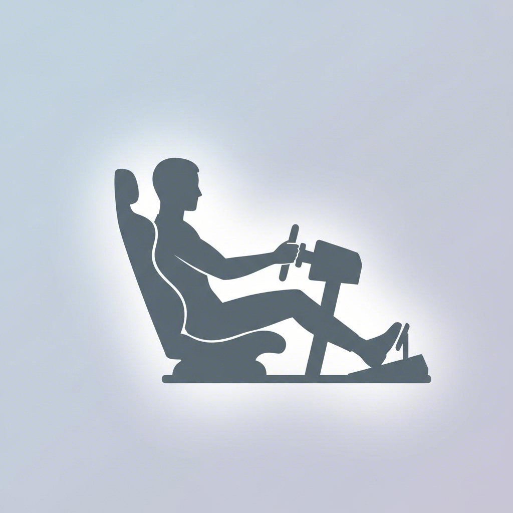
You've selected your profile sizes and understand your materials. Now comes the moment that separates comfortable, fast rigs from awkward builds you'll constantly fight against: translating your body dimensions into precise extrusion lengths. Whether you're working from diy sim rig plans free resources or designing from scratch, proper ergonomic planning makes the difference between a cockpit that feels like an extension of your body and one that causes fatigue after thirty minutes.
Think about this: professional racing drivers have their cockpits custom-fitted to millimeter precision. Formula 1 drivers use carbon fiber seats molded to their exact body shape, with every control positioned for optimal reach and minimal strain. Your 8020 sim rig plans should follow the same principle, scaled to your specific measurements and equipment.
Before cutting a single piece of aluminum, you need baseline measurements that account for your height, limb proportions, and preferred driving style. GT-style and Formula-style seating positions require fundamentally different frame geometries, so deciding your approach first prevents costly mistakes.
GT-style positioning mimics road cars and GT racing vehicles with a more upright seat angle (typically 15-25 degrees from vertical). This position places the wheel lower relative to your shoulders and keeps pedals closer to horizontal. Most sim racers prefer this setup for its versatility across different racing disciplines.
Formula-style positioning replicates open-wheel racing with a heavily reclined seat (40-60 degrees from vertical). Your legs extend nearly straight toward raised pedals, and the wheel sits higher relative to your chest. This aggressive position works brilliantly for dedicated formula sim racing but feels cramped for longer GT endurance sessions.
Follow this step-by-step measurement process to establish your baseline dimensions:
According to sim racing ergonomics research, your elbows should stay slightly bent with hands resting naturally on the wheel, and your knees should remain slightly bent with feet flat on the pedals. These positions minimize strain during extended sessions and maximize control precision.
With baseline measurements recorded, you can calculate the specific angles and heights that transform raw dimensions into comfortable driving positions.
Pedal deck angle significantly impacts braking feel and throttle control. Most sim racers find optimal comfort between 35-50 degrees from horizontal for GT-style setups. Formula-style builds often use steeper angles approaching 60-70 degrees. Your pedal deck frame length depends on this angle combined with your hip-to-heel measurement.
Wheel mount height should position the wheel rim center approximately level with your shoulders for GT-style builds. When seated with arms extended toward the wheel, your wrists should rest on top of the rim without raising your shoulders. Formula-style setups raise the wheel 10-15cm higher relative to seat position.
Monitor positioning follows a simple rule: your eyes should align with the center or upper third of your monitor. The optimal viewing distance sits around 60-70cm depending on screen size and your field of view settings. These measurements determine your monitor mount extension length and height adjustment range.
Translating ergonomic measurements into actual extrusion lengths requires accounting for profile thickness, bracket offsets, and equipment mounting dimensions. Detailed sim rig blueprints typically include these calculations, but understanding the process helps you adapt any plan to your specific needs.
Start by documenting your equipment dimensions. Measure your wheel base mounting hole pattern, pedal set footprint, and seat rail spacing. These fixed dimensions constrain certain frame measurements regardless of your body size. Add 50-100mm clearance around equipment for adjustment range and cable routing.
Your sim racing cockpit plans should account for these hardware categories in your bill of materials:
Hardware quantities depend heavily on your specific design. A basic rig might use 80-120 T-nuts and 40-60 brackets, while complex builds with multiple accessory mounts could require twice that amount. When developing diy sim rig plans, add 15-20% extra hardware to account for design changes during assembly.
One experienced builder noted that just extrusions alone cost over $600 for a 40-series build before adding hardware like T-nuts, bolts, brackets, and mounting plates. By the time everything was accounted for, the frame approached $1,000. Understanding this complete cost picture helps you budget realistically and decide between DIY construction and pre-made alternatives.
With your measurements calculated and materials list drafted, you're positioned to make informed decisions about your build approach. But before finalizing your 80 20 sim rig plans, it's worth understanding how aluminum compares to alternative materials that might suit your specific situation better.
Now that you understand aluminum profiles, grades, and ergonomic planning, a fair question emerges: is an 80 20 sim rig actually the best choice for your situation? Aluminum extrusion dominates online discussions, but steel frames and wood cockpits each serve specific needs that deserve honest consideration. Making the right material choice upfront saves you from expensive rebuilds later.
Every material brings distinct advantages and compromises to sim racing cockpit construction. Steel delivers maximum rigidity at lower cost. Wood offers budget-friendly accessibility for DIY builders. An aluminum sim rig provides the modularity and upgrade potential that serious enthusiasts crave. Understanding where each material excels helps you match your choice to your actual priorities rather than following trends blindly.
Let's break down how these three materials compare across the factors that matter most for sim racing performance and long-term satisfaction.
| Factor | Aluminum Extrusion | Steel Tubing | Wood (Plywood/MDF) |
|---|---|---|---|
| Weight | Moderate (25-40 lbs typical frame) | Heavy (40-60+ lbs typical frame) | Light to Moderate (varies by thickness) |
| Rigidity | Excellent when properly braced | Superior, especially welded joints | Good for light equipment, prone to flex under high loads |
| Modularity | Exceptional (infinite adjustment points) | Very Limited (fixed structure) | Limited (requires new cuts/holes) |
| Cost | $400-$1,200+ for complete frame | $200-$800 for comparable rigidity | $50-$200 for materials |
| Ease of Modification | Simple (loosen bolts, reposition) | Difficult (requires welding/cutting) | Moderate (requires woodworking tools) |
| Aesthetic Options | Anodized colors, powder coating, industrial look | Paint, powder coating, professional appearance | Paint, veneer, stain, DIY customization |
| Lifespan | 10+ years with minimal maintenance | 10+ years if rust-protected | 3-7 years depending on humidity and use |
| Resale Value | High (modular components retain value) | Moderate (size limits buyer pool) | Low (custom dimensions rarely fit others) |
According to industry analysis, steel-framed cockpits with 40x40mm or 45x45mm square tubing outperform thinner aluminum profiles in long-term durability under sustained loads. However, this comparison assumes equivalent profile sizes. When you match an 80 20 rig built with 80x80mm aluminum against typical steel tube frames, the rigidity gap narrows considerably while aluminum maintains its modularity advantage.
Choosing your cockpit material isn't about finding the "best" option—it's about matching the material to your specific circumstances, budget, and long-term plans.
Wood cockpits make sense when you're testing the sim racing waters without major financial commitment. If you already own woodworking tools and have basic construction skills, you can build a functional rig for under $200 in materials. Plywood and MDF cut easily, accept standard hardware store fasteners, and allow complete design freedom.
The limitations become apparent as your equipment upgrades. Wood handles belt-driven wheel bases and basic pedals adequately, but wooden versions may degrade faster due to humidity or develop stress cracks under the sustained forces from direct drive systems. If you're running entry-level Logitech or Thrustmaster equipment with no immediate upgrade plans, a well-constructed wood cockpit serves its purpose. Just understand you'll likely rebuild when moving to serious hardware.
Steel frames excel when you've finalized your setup and don't anticipate major changes. A properly welded steel cockpit offers unmatched rigidity at a lower price point than comparable aluminum builds. The metal rig approach works particularly well for commercial sim centers or dedicated sim rooms where the cockpit won't move.
The trade-off is permanence. Want to adjust your pedal position by two inches? With steel, you're looking at cutting, grinding, and re-welding. Need to add a shifter mount you didn't originally plan for? Hope you have welding equipment and skills. Steel cockpits lock you into decisions made during construction, which explains why they dominate commercial installations where professional setup ensures everything is right the first time.
Steel also carries weight implications. Moving a 60+ pound frame requires effort and planning. If your sim racing space might change, or if you rent your living space, steel's permanence becomes a liability rather than an asset.
An 80 20 rig shines brightest for enthusiasts who view sim racing as an evolving hobby rather than a static setup. The T-slot system transforms your cockpit into a platform that grows with your ambitions and adapts to new equipment without structural compromises.
Consider the upgrade path examples that aluminum enables:
The modularity advantage extends beyond hardware changes. Modular frames let you add new gear like shifters, extra monitors, or motion platforms without needing to start from scratch. This flexibility means your racing rig sim can easily evolve as new tech hits the market, protecting your initial investment while keeping you at the cutting edge.
Perhaps most importantly for many enthusiasts, aluminum components retain strong resale value. Individual profiles, brackets, and accessories sell readily on secondary markets. If you decide to reconfigure or upgrade, you're recovering investment rather than discarding custom-cut steel or plywood that fits no one else's needs.
The higher upfront cost of an aluminum extrusion sim racing rig pays dividends through adaptability, longevity, and resale potential. For anyone planning to stay in the hobby long-term and anticipating equipment evolution, the T-slot system provides a foundation that grows with you rather than holding you back.
With material selection clarified, the next critical consideration involves ensuring your chosen profiles and frame design actually accommodate your specific equipment. Hardware compatibility determines whether your beautiful aluminum cockpit performs flawlessly or frustrates you with mounting challenges.
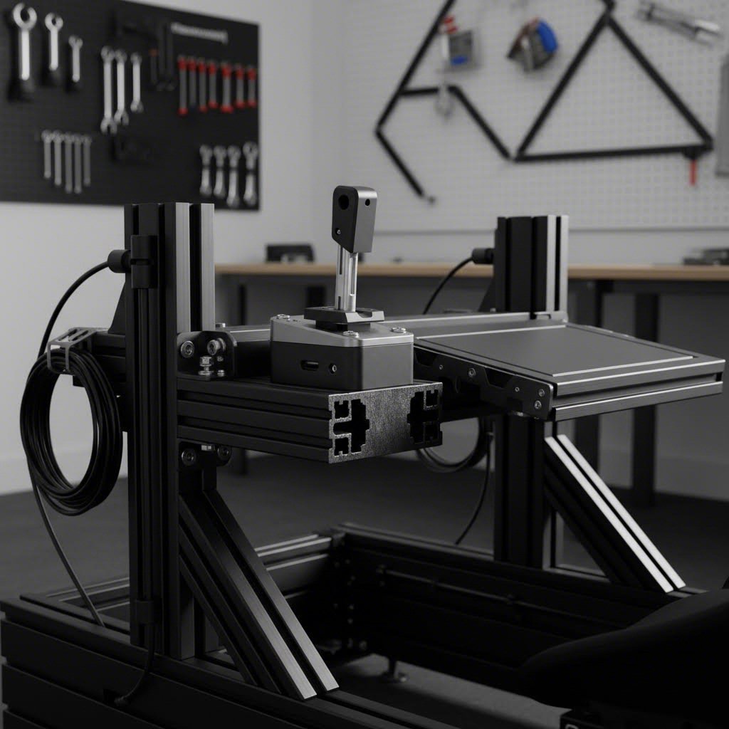
You've planned your frame dimensions and selected your materials. But here's where many builders hit unexpected roadblocks: discovering their carefully designed profile rig doesn't accommodate their wheel base mounting pattern, or their pedal set requires awkward adapter plates. Hardware compatibility might seem like a minor detail until you're staring at misaligned bolt holes and scrambling for solutions.
The beauty of an 8020 rig lies in its adaptability, but that flexibility only matters when you understand which profiles and mounting solutions work with your specific equipment. Let's eliminate the guesswork by examining exactly how popular sim racing hardware integrates with aluminum extrusion systems.
Direct drive wheel bases from major manufacturers share similar mounting principles but differ in bolt patterns and clearance requirements. Understanding these specifications before finalizing your 8020 racing rig design prevents frustrating surprises during assembly.
Fanatec DD Series: The DD1, DD2, and CSL DD use a standard four-bolt mounting pattern that fits most aftermarket wheel deck plates designed for 40-series profiles. The CSL DD's compact footprint works with 40x80mm wheel mounts, while the larger DD1/DD2 units benefit from 80x80mm profiles for maximum rigidity. Side-mounting options exist for hard-mounted installations where the motor extends forward rather than sitting atop a plate.
Simucube Series: Simucube 2 Sport, Pro, and Ultimate models feature a centered mounting pattern that requires specific adapter plates or dedicated Simucube-compatible wheel decks. These high-torque units (up to 32Nm for the Ultimate) demand 80x80mm minimum profile sizing at the wheel mount. Many builders incorporate triangular gusset bracing behind the wheel deck to eliminate any possibility of flex.
Moza Racing: The R9, R12, and R16 wheel bases use a mounting pattern compatible with many universal wheel deck designs. These units work well with 40x80mm profiles for the R9 and R12, while the R16's higher torque output benefits from 80x80mm construction. Moza's ecosystem includes purpose-built mounting solutions that bolt directly to 40-series extrusions.
Pedal mounting follows similar considerations. Load cell pedal sets like the Heusinkveld Sprints, Fanatec ClubSport V3, and Simucube ActivePedal generate significant forces during threshold braking. Your pedal deck should incorporate 40x80mm or larger profiles running perpendicular to the braking direction, with reinforcing cross-members preventing any twisting motion.
Beyond core equipment, the accessory ecosystem transforms a basic cockpit into a fully-featured simulator. Each accessory category has specific profile compatibility and mounting considerations worth understanding before you finalize your design.
Not everyone has a dedicated sim room. If you're working with limited space, your 8020 racing rig design needs to accommodate real-world constraints like desk proximity, room traffic patterns, and storage requirements.
Desk-mounted configurations eliminate the need for a full cockpit footprint. Wheel stand designs using 40x80mm profiles can slide under a desk when not in use, while still providing excellent rigidity during racing sessions. Some builders create hybrid setups where the wheel mount attaches to a desk-height frame that shares space with their everyday computer workstation.
Folding or partially collapsible designs sacrifice some rigidity for practicality. Strategic use of quick-release pins or cam-lock handles at key joints allows sections of your profile rig to fold or detach for storage. The trade-off involves slightly more complex assembly and potentially reduced stiffness compared to fully bolted configurations.
For truly tight spaces, vertical storage becomes an option. Some builders design their cockpits to roll on casters and stand upright against a wall when not in use. This approach requires careful weight distribution planning and secure locking mechanisms to prevent accidents.
Here's an often-ignored topic that separates clean builds from tangled messes: routing cables through and along your aluminum extrusion frame. Those T-slots aren't just for mounting hardware. They create perfect channels for organizing the substantial wiring that modern sim setups generate.
USB cables, power cords, pedal connections, and button box wiring add up quickly. Without proper management, you'll end up with a spider web of cables that looks unprofessional and creates tripping hazards. Aluminum profiles offer elegant solutions:
Plan your cable routing during the design phase rather than as an afterthought. Identify where each connection originates, where it terminates, and what path it should follow. This forethought results in a cleaner, more professional-looking build that's easier to troubleshoot if connection issues arise later.
With hardware compatibility and accessory integration understood, the next consideration involves budgeting realistically for your build and deciding whether DIY component sourcing or pre-made kits better suit your situation.
You've mapped out your ideal driving position and understand which profiles handle your equipment's demands. Now comes the question that shapes every build decision: how much should you actually spend? The aluminum extrusion sim racing rig market spans from budget-friendly options under $500 to premium builds exceeding $1,500. Knowing what each tier delivers helps you invest wisely rather than overspending on features you don't need or under-buying and regretting it later.
Beyond budget, you face another fundamental choice: purchase a complete kit from established manufacturers or source individual components for a custom DIY build. Each path offers distinct advantages depending on your priorities, skills, and long-term sim racing goals.
The sim rig market has matured significantly, creating clear performance tiers that match different equipment levels and commitment depths. Understanding what you're getting at each price point prevents disappointment and ensures your cockpit matches your ambitions.
| Budget Tier | Typical Investment | Profile Sizes Included | Suitable Equipment Level | Upgrade Potential |
|---|---|---|---|---|
| Entry-Level | $400-$600 | 40x40mm, 40x80mm | Belt-driven wheels up to 8Nm, basic load cell pedals | Moderate - may require reinforcement for DD upgrades |
| Mid-Range | $600-$1,000 | 40x80mm, 40x120mm | Entry direct drive up to 15Nm, quality load cell pedals | Good - handles most equipment without modification |
| Premium | $1,000-$1,500+ | 40x120mm, 40x160mm | High-end direct drive 20Nm+, hydraulic pedals, motion platforms | Excellent - future-proofed for any foreseeable upgrade |
Entry-level builds like the Trak Racer TR80 or GT Omega Prime Lite provide solid foundations for sim racers transitioning from wheel stands or basic cockpits. These rigs handle belt-driven equipment confidently and work reasonably well with entry-level direct drive bases. The trade-off appears when you upgrade to high-torque wheel bases. Smaller 40x40mm profiles in critical areas may develop subtle flex that wasn't noticeable with gentler equipment.
Mid-range options represent the sweet spot for most enthusiasts. The Sim-Lab GT1 Pro exemplifies this tier, using 40x40mm and 40x80mm profiles in a configuration that handles very strong forces without exhibiting flex commonly found in cheaper sim rigs. At this level, you're investing in a platform that accommodates equipment upgrades without requiring structural modifications. Pre-drilled mounting plates accept most popular wheel bases, and pedal deck construction handles aggressive load cell braking.
Premium builds like the Sim-Lab P1X Pro or Next Level Racing F-GT Elite 160 use oversized 40x160mm profiles that eliminate flex entirely, even with professional-grade direct drive systems pushing past 20Nm. The P1X Pro specifically offers performance beyond most other cockpits with almost zero flex or vibrations. These rigs arrive motion-ready, meaning you can add a motion platform without structural concerns. The investment makes sense if you're running high-end equipment now or planning to reach that level within the next few years.
Once you've identified your budget tier, another decision emerges: should you purchase a complete kit from manufacturers like Rigmetal or Sim-Lab, or source components individually for a fully custom build? Both approaches have passionate advocates, and the right choice depends on your specific situation.
A rigmetal sim rig or similar kit purchase makes excellent sense for builders who value convenience and proven performance over maximum customization. When you order a complete package, you're paying for engineering work already completed. Someone else calculated the profile sizes, hardware quantities, and structural requirements. You're simply assembling tested components according to documented procedures.
DIY builds reward experienced builders who have specific requirements that off-the-shelf kits don't address. Perhaps your sim space has unusual dimensions, or you want to integrate features that commercial designs don't include. The DIY path also appeals to builders who enjoy the engineering challenge as much as the end result.
Regardless of which path you choose, selecting initial profiles with future upgrades in mind protects your investment. The goal is avoiding situations where equipment upgrades force complete frame replacements.
Consider where your sim racing journey might lead over the next three to five years. If you're currently running a belt-driven wheel but eyeing direct drive systems, starting with 40x80mm profiles at your wheel mount costs marginally more now but prevents reinforcement headaches later. Similarly, building your main frame rails from 40x80mm or larger profiles ensures compatibility with motion platforms you might add down the road.
The Sim-Lab 80 20 ecosystem illustrates thoughtful future-proofing. Their GT1 Pro serves as an entry point that handles mid-range equipment admirably, while the P1X Pro provides the upgrade path for those who eventually pursue professional-grade performance. Both rigs share accessory compatibility, meaning shifter mounts, monitor stands, and other peripherals transfer between platforms.
Think about profile series compatibility when sourcing components. Mixing 40-series and 45-series extrusions creates hardware headaches since their T-slot dimensions differ. Standardizing on one series, typically 40-series for sim racing applications, ensures every bracket and accessory you own works anywhere on your rig.
Your decision between a rigmetal basic configuration or premium alternative ultimately depends on honest self-assessment: how committed are you to sim racing, what equipment do you realistically plan to run, and how much value do you place on convenience versus customization? There's no universally correct answer, only the choice that best matches your individual circumstances.
With budget and build path decisions made, one challenge remains that catches many builders off guard: ensuring your assembled rig actually performs as expected. Understanding common assembly issues and how to eliminate flex completes your preparation for a successful build.
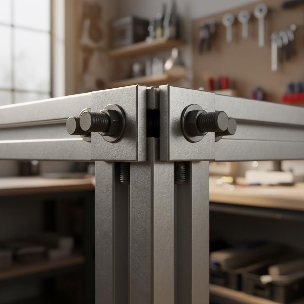
You've invested in quality profiles, planned your ergonomics carefully, and assembled your 80/20 sim rig with enthusiasm. But something feels wrong. During hard braking, your pedal deck shifts slightly. Aggressive force feedback creates subtle movement at the wheel mount. That rock-solid experience you expected? It's not quite there. Don't worry. These issues plague even experienced builders, and they're almost always fixable without starting over.
The single most important factor in any extruded aluminum sim rig is rigidity. As sim racing experts emphasize, the higher the quality of the rig, the better the rigidity and the less flex in the frame between seat and pedals or seat and wheelbase. Even a few millimeters of flex might seem negligible, but that movement absorbs force feedback information that should reach your hands and dampens the precise pedal feel you paid good money to experience.
Before grabbing your wrenches, identify exactly where flex occurs. Random tightening wastes time and might miss the actual problem. Systematic diagnosis leads to targeted solutions.
Start with this simple test: sit in your rig and apply maximum brake pressure while watching different frame sections. Have a friend observe, or set up your phone to record. Note any movement at connection points, along profile lengths, or where equipment mounts to the frame. Repeat the test while making aggressive steering inputs with your wheel base at maximum force feedback strength.
Common symptoms of inadequate rigidity and their typical causes include:
Once you've identified the problem area, you can apply targeted fixes rather than over-engineering your entire sim racing aluminum rig.
The most common cause of rig flex isn't undersized profiles or poor design. It's improperly installed T-nuts. These small components carry enormous responsibility, and getting them right transforms a wobbly build into a solid platform.
T-nuts work by sliding into the profile slot, then rotating 90 degrees so their flanges catch under the slot shoulders. When you tighten the bolt, the nut pulls up against the slot, creating a clamping force that locks everything together. Problems arise when this sequence doesn't happen correctly.
According to T-slot engineering guidelines, proper bolt tension ensures a strong and lasting connection. Under-tightened bolts allow components to shift under load. Over-tightened bolts can strip threads or crack T-nut flanges, especially with lower-quality hardware.
Follow these installation best practices for your alu sim rig:
Beyond T-nut issues, several assembly errors consistently undermine rigidity in otherwise well-designed builds. Recognizing these patterns helps you avoid them entirely or fix existing problems.
What if you've already built your rig and discovered flex issues? Complete rebuilds rarely become necessary. Strategic reinforcement addresses most problems without starting over.
For pedal deck flex, the most effective solution involves adding triangular gusset plates between the pedal deck surface and the main frame uprights. These plates transfer braking forces directly into the main structure rather than relying solely on the T-nut connections at the deck's rear edge. Position gussets at 45-degree angles for maximum effectiveness.
Wheel mount flex responds well to additional bracing behind the wheel deck plate. If your current setup uses only the standard four-bolt pattern, consider adding vertical supports that tie the wheel deck directly to the main frame rails below. Some builders fabricate custom reinforcement plates that extend the wheel deck's footprint onto additional profile surfaces.
Frame rocking typically indicates inadequate base construction. Before adding profile extensions, check whether simply tightening existing connections resolves the issue. If the base frame is structurally sound but still rocks, adding outrigger feet or weight at the base corners improves stability. Rubber anti-vibration pads under the frame feet both dampen vibration and prevent sliding on hard floors.
Understanding how forces travel through your rig helps you identify weak points before they become problems. Every force applied to your cockpit follows a path through the structure to the floor. Interruptions or weak links in that path create flex.
When you brake hard, the force travels from your foot through the pedal, into the pedal deck, through the mounting connections, along the main frame rails, and finally into the floor. Any connection along this path that can't handle the load becomes a flex point. The same principle applies to steering inputs, which travel from the wheel through the mounting plate, into the wheel deck supports, and down to the base frame.
Proper load paths follow the shortest practical route with the fewest connection points. Long, unsupported spans create leverage that amplifies small connection movements into noticeable flex. Triangulated structures resist deformation better than rectangular ones because forces distribute across multiple members rather than concentrating at corners.
Consider your seated weight distribution as well. Your body weight concentrates primarily through the seat mounting points and partially through the pedals when not braking. If seat mounting connections are weaker than wheel or pedal connections, lateral forces during cornering can create unexpected movement. Balance your reinforcement efforts across all major load-bearing areas rather than over-engineering just one section.
The difference between a mediocre alu sim rig and an exceptional one often comes down to these details. Proper T-nut installation, strategic bracing, and thoughtful load path design transform commodity aluminum profiles into a platform that rivals professional installations. With your assembly optimized for maximum rigidity, the final step involves sourcing the quality materials that make this performance possible.
You've mastered profile selection, planned your ergonomics, and understand how to eliminate flex. Now comes the final piece of the puzzle: finding a supplier who can deliver the quality aluminum extrusions your build demands. The difference between a frustrating project and a flawless assembly often comes down to where you source your materials. Precision matters when every cut must align perfectly and every surface treatment needs to withstand years of intensive use.
Whether you're building a complete aluminum sim racing cockpit from scratch or adding custom components to an existing setup, your supplier relationship shapes the entire experience. Let's explore what separates adequate vendors from exceptional partners who elevate your 8020 cockpit project.
The aluminum extrusion market includes everything from industrial distributors with warehouse stock to specialized manufacturers offering custom processing services. Understanding your options helps you match supplier capabilities to your specific project requirements.
Industrial distributors stock standard profile lengths and sizes for immediate shipping. This approach works well when you need common 8020 aluminum profile dimensions and can handle cutting yourself. The trade-off involves limited customization and the need for your own fabrication equipment.
Custom extrusion manufacturers offer end-to-end services from raw material to finished components. According to industry specialists, the best suppliers provide drilling, punching, countersinking, bending, and forming to your exact specifications. This means receiving components ready for immediate assembly rather than spending hours with measuring tools and cutting equipment.
For aluminum sim cockpit builders, several sourcing factors deserve careful evaluation:
As experienced manufacturers note, custom extrusion orders often involve complex combinations of fabrication, color, and finish that not all suppliers can handle profitably at smaller quantities. Finding a partner willing to work with individual builders rather than only serving industrial accounts makes the difference between a smooth project and endless frustration.
Beyond basic material supply, the right processing partner transforms your aluminum racing sim cockpit vision into reality. Modern CNC machining capabilities enable precision that hand tools simply cannot match, while professional surface treatments create finishes that protect your investment and enhance aesthetics.
CNC machining services handle operations that would otherwise require specialized equipment and skills. Advanced 5-axis CNC equipment can produce tight-tolerance features on complex extrusion shapes, including mounting holes drilled at precise locations, countersunk fastener pockets, and custom profile modifications. This level of precision ensures your wheel base mounting pattern aligns perfectly the first time.
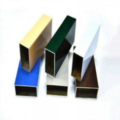
Surface treatment options extend far beyond raw aluminum. Professional anodizing creates a protective oxide layer that resists scratches, fingerprints, and corrosion while offering color customization possibilities. Powder coating provides even more extensive color options with excellent durability for high-wear areas. These finishes transform industrial-looking profiles into polished cockpit components that complement your sim racing setup aesthetically.
For DIY builders seeking quality materials with professional processing, Shengxin Aluminium represents exactly the type of partner worth considering. With over 30 years of industry experience and 35 advanced extrusion presses ranging from 600T to 5500T capacity, they offer the manufacturing depth that ensures consistent quality across your entire order. Their state-of-the-art CNC machining centers handle precise cutting and drilling to your exact specifications, eliminating the need for DIY fabrication.
What sets specialized processors apart is their surface treatment variety. Shengxin's anodizing capabilities include custom colors like Champagne and Rose Gold alongside standard options, while their powder coating and PVDF treatments provide additional durability choices. For builders creating personalized 8020 cockpit designs, this flexibility means matching your rig to existing room aesthetics or gaming setup color schemes.
Their 6063 aluminum expertise proves particularly relevant for sim racing applications. As we discussed earlier, 6063-T5 delivers the ideal combination of extrudability, surface finish quality, and corrosion resistance that T-slot profiles require. Factory-direct pricing from experienced manufacturers like Shengxin often undercuts distributors who add markup layers between you and the production source.
When selecting an aluminum processing partner for your sim racing project, prioritize suppliers who offer precision CNC cutting to tight tolerances, professional surface treatment options, and flexibility for individual builder quantities. The right partner delivers components ready for immediate assembly rather than raw materials requiring additional fabrication.
Your aluminum sim racing cockpit represents a significant investment of time, money, and enthusiasm. Sourcing quality materials from capable processing partners protects that investment while simplifying your build process. Whether you're creating a complete custom design or modifying an existing rig, the foundation starts with premium 6063 aluminum extrusions cut and finished to professional standards.
Throughout this guide, you've gained the knowledge needed to plan, build, and optimize an aluminum extrusion sim racing rig that delivers zero-flex performance. From understanding profile sizes and material specifications to planning ergonomic layouts and troubleshooting assembly issues, you're now equipped to create a cockpit that matches professional installations. The modular T-slot system you choose today becomes the platform for years of sim racing evolution, adapting to new equipment and expanding capabilities as your skills and ambitions grow. Your next step? Start translating this knowledge into action, one precisely-cut profile at a time.
Building your own aluminum extrusion sim rig can save 30-50% compared to pre-made alternatives while offering complete customization. However, factor in hidden costs like T-nuts, brackets, bolts, and shipping from multiple suppliers. DIY builds reward experienced builders who need specific dimensions or features that commercial kits don't offer. For most enthusiasts, the learning experience and exact-fit ergonomics justify the extra planning effort. If convenience matters more, pre-made kits from manufacturers like Sim-Lab or Rigmetal provide tested designs with guaranteed compatibility.
Profile size depends on your equipment's torque output. For belt-driven wheel bases up to 8Nm, 4040 profiles work adequately. Entry to mid-level direct drive bases (8-15Nm) require 40x80mm profiles at wheel mounts and pedal decks. High-end direct drive systems pushing 20Nm or more demand 80x80mm profiles in critical structural areas. The 40-series metric profiles with 8mm slots represent the most common choice for sim racing due to excellent accessory compatibility and the ideal balance of strength, weight, and cost.
6063-T5 aluminum is the industry standard for T-slot extrusions, offering superior extrudability, excellent surface finish, and enhanced corrosion resistance. 6061-T6 provides approximately 30% higher tensile strength but is less common in T-slot profiles due to manufacturing challenges. For sim racing applications, 6063-T5 delivers more than enough rigidity when properly sized profiles are used. The practical difference becomes negligible since increasing profile dimensions provides greater rigidity gains than switching alloys while maintaining better surface treatment compatibility.
Flex typically stems from improperly installed T-nuts, insufficient corner bracing, or undersized profiles. First, verify all T-nuts have fully rotated and apply 15-20Nm torque on M8 bolts. Add triangular gusset plates at high-stress connections, especially wheel mounts and pedal decks. Incorporate diagonal bracing to prevent parallelogram deformation in rectangular frame sections. For persistent issues, reinforce with additional cross-members every 400-500mm on long profile spans. Quality hardware matters—premium T-nuts and bolts provide dramatically better clamping force than budget alternatives.
Pre-made kits offer guaranteed compatibility, clear instructions, and manufacturer warranty support, making them ideal for first-time builders or those valuing convenience. Complete kits from Sim-Lab, Rigmetal, or Next Level Racing provide tested designs validated by thousands of users. DIY component sourcing suits experienced builders needing specific dimensions, unique features, or maximum cost control. Consider that DIY builds require calculating hardware quantities, managing multiple suppliers, and accepting full responsibility for design decisions. Most enthusiasts find mid-range pre-made kits offer the best balance of value and simplicity.



 خدمة الإنترنت
 0086 136 3563 2360
 sales@sxalu.com
 +86 136 3563 2360
 العربية
 English
 français
 Deutsch
 русский
 español
 português
 ไทย
ไทย Việt
Việt Українська