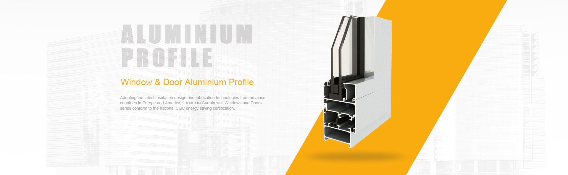

Imagine squeezing toothpaste from a tube. The paste emerges in a consistent shape determined by the opening. Now scale that concept up to industrial manufacturing, replace toothpaste with heated aluminum, and you've got the basic idea behind aluminum extrusion. But here's the thing—getting that shape right from the very beginning? That's where aluminum extrusion profile design becomes absolutely critical.
So, how do we define extruded aluminum in practical terms? It's a manufacturing process where heated aluminum alloy is forced through a specially shaped die to create parts with a consistent cross-sectional profile. The aluminium extrusion definition extends beyond just the process itself—it encompasses the entire discipline of designing those cross-sections to meet structural, aesthetic, and manufacturing requirements.
Aluminum extrusion profile design is the engineering discipline focused on creating optimal cross-sectional shapes for extruded aluminum components. It combines material science, manufacturing knowledge, and application-specific requirements into a unified design approach. Whether you're an engineer developing industrial machinery, an architect specifying building facades, or a product designer creating consumer goods, understanding this discipline directly impacts your project's success.
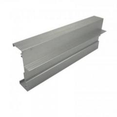
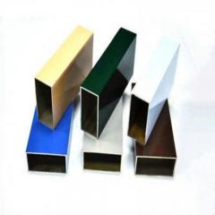
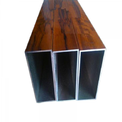
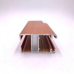
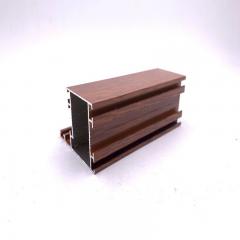
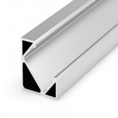
The beauty of extruded aluminum lies in its versatility. A square die produces continuous square tubes ideal for frames and supports, while T- or U-shaped dies create profiles suitable for structural framing or sliding tracks. The possibilities span from simple solid bars to incredibly complex hollow sections with integrated channels, snap-fit features, and mounting points.
Here's what many designers overlook: the geometry you choose in the design phase ripples through every subsequent step of your project. Get it right, and you'll enjoy smooth manufacturing, predictable costs, and excellent performance. Get it wrong, and you're looking at expensive die modifications, production delays, or worst of all—parts that don't perform as intended.
Proper aluminum extrusion design reduces manufacturing costs by up to 30% while simultaneously improving structural performance. The key is optimizing your profile geometry before die fabrication begins—not after.
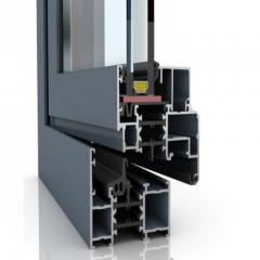
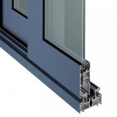
Aluminum extrusion profiles appear everywhere once you start looking. Window frames, door systems, heat sinks for electronics, aircraft components, bicycle frames, and automotive structures all rely on carefully designed aluminum extrusion shapes. Each application demands specific geometric considerations that balance strength, weight, manufacturability, and cost.
Understanding the extrusion process helps you make smarter design decisions. It starts with a cylindrical aluminum billet—preheated to approximately 450-500°C until it becomes malleable but not molten. A hydraulic ram then applies up to 15,000 tons of pressure, forcing the heated aluminum through the die opening. The material emerges fully formed, maintaining that exact cross-section continuously.
After exiting the press, the aluminum extrusion undergoes quenching (rapid cooling), stretching to correct any distortions, and cutting to specified lengths. Surface treatments like anodizing or powder coating often follow, enhancing both appearance and corrosion resistance.
Throughout this guide, you'll learn the classification systems for different profile types, critical dimensional parameters that prevent manufacturing failures, alloy selection strategies, and design-for-manufacturability principles. By the end, you'll have a complete framework for taking your aluminum extrusion design from initial concept to production-ready specifications.

Now that you understand the fundamentals, let's explore the three distinct categories of aluminum extrusion shapes. This classification system isn't just academic—it directly influences your die costs, production speeds, and ultimately, your project budget. Choosing the right profile category early in the design process can save you thousands of dollars and weeks of production time.
Solid profiles are exactly what they sound like—extruded shapes without any enclosed voids or openings. Think angles, flat bars, channels, and T-bars. These types of aluminum extrusions represent the most straightforward manufacturing approach because they require the simplest die configurations.
Why should you consider solid profiles first? They offer several compelling advantages:
Here's something competitors often overlook: even seemingly simple solid shapes require careful attention to wall thickness balance and symmetry. An asymmetric solid profile can cause uneven metal flow, leading to twisting or bowing during extrusion. When designing solid extrusion shapes, aim for balanced cross-sections whenever possible.
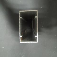
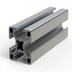
Hollow profiles contain one or more fully enclosed voids—rectangular tubes, round tubes, and complex multi-void t-slot profiles all fall into this category. These extruded aluminum shapes require porthole dies consisting of two interlocking pieces: a mandrel that forms internal features and a cap that creates external surfaces.
Semi-hollow profiles occupy the middle ground. They have voids that aren't fully enclosed—imagine a narrow channel or a C-shaped section with a small gap. But how do manufacturers distinguish between a solid channel and a semi-hollow one?
The answer lies in the tongue ratio, calculated as Area/Gap². According to industry specifications, the larger the void area and the narrower the gap, the higher the tongue ratio—and the more likely the shape qualifies as semi-hollow. This matters because high tongue ratios create stress concentrations in the die, making the tongue area prone to breakage under the intense pressure of extrusion.
Selecting the right profile type involves balancing performance requirements against manufacturing realities. Use this comparison to guide your decision:
| Profile Type | Typical Applications | Design Complexity | Cost Considerations |
|---|---|---|---|
| Solid | Angles, channels, flat bars, heat sink fins, decorative trim | Low—simple flat-face or pocket dies | Lowest die cost, fastest extrusion speeds, longest die life |
| Hollow | Structural tubes, t-slot framing, window frames, enclosures | High—requires mandrel and cap assembly | Higher die cost, moderate speeds, more complex tolerancing |
| Semi-Hollow | Narrow channels, complex architectural sections, snap-fit housings | Medium to High—depends on tongue ratio | Variable—increases with tongue ratio; may require reinforced tooling |
Beyond shape category, the circumscribing circle diameter (CCD) significantly impacts your options. The CCD is simply the diameter of the smallest circle that completely encloses your profile's cross-section. According to the Aluminum Extruders Council, most economical profiles fit within a CCD between one and ten inches, with profiles under 8 inches offering the most cost-effective production. Larger CCDs require bigger presses—and fewer facilities have the capacity for profiles exceeding 20 inches.
Weight-per-foot also affects press selection and economics. Generally, keeping your profile CCD under 8 inches with a weight of 3 pounds per foot or less positions you for optimal manufacturing efficiency. Armed with this classification framework, you're ready to dive into the specific dimensional parameters that determine whether your chosen profile type will extrude successfully.
You've selected your profile category and understand the classification system—but here's where many designers stumble. The difference between an extruded aluminum profile that runs smoothly through production and one that causes endless headaches often comes down to specific dimensional parameters. Get these numbers wrong, and you'll face warped sections, cracked dies, or profiles that simply won't extrude at all.
Think of these parameters as the rules of the road for aluminum extrusion dimensions. Some are flexible guidelines; others are hard limits dictated by physics and material properties. Let's break down exactly what you need to know to specify dimensions that work.
Wall thickness is arguably the most critical dimension in your entire profile design. Too thin, and the metal won't flow properly through the die—or worse, your part lacks the structural integrity needed for its intended application. Too thick, and you're wasting material while potentially creating cooling imbalances that cause warping.
Minimum wall thickness depends on several factors, but alloy choice and circumscribing circle diameter (CCD) are the primary drivers. For the most commonly extruded alloys—6060 and 6063—you can achieve thinner walls than with higher-strength alloys like 6061 or 6082. Here's why: softer alloys flow more readily through narrow die openings.
According to Australian Aluminium Council guidelines, minimum metal thickness follows a predictable relationship with CCD:
Beyond minimums, you'll also want to avoid dramatic thickness variations within a single profile. When your design combines thick and thin sections, aim for adjacent-wall thickness ratios of less than 2:1 for optimal extrusion. Larger contrasts create uneven metal flow, potentially causing surface defects or dimensional inconsistencies. When thickness changes are unavoidable, use generous transition radii—never abrupt steps—to blend thick and thin areas together.
Sharp corners might look clean on your CAD screen, but they create serious problems during extrusion. From a manufacturing standpoint, sharp internal corners concentrate stress in the die, dramatically shortening its lifespan. Sharp external corners cause metal flow disruptions that produce visible die lines and surface imperfections.
The rule of thumb? Always break sharp corners with a radius. Even a minimal 0.5mm radius significantly improves extrusion conditions, but larger radii are preferred when your design allows. For architectural applications requiring anodized finishes, sharp corners produce obvious sight lines in the coating—another reason to specify appropriate radii from the start.
Per industry tolerance standards, corner and fillet radii tolerances follow these specifications:
For semi-hollow profiles, the tongue ratio becomes critically important. Remember, tongue ratio equals Area/Gap². Industry recommendations suggest keeping this ratio at 3:1 or lower for reliable extrusion, though readily extruded alloys like 6060 sometimes allow higher ratios. When your design approaches or exceeds 3:1, consult with your extrusion manufacturer early—they may recommend design modifications or reinforced die construction.
Understanding aluminum extrusion tolerances separates experienced designers from novices. Standard industry tolerances work perfectly for most applications, but specifying them incorrectly—or demanding precision tolerances when they're unnecessary—directly impacts your costs and lead times.
The tolerance tables in Aluminum Standards & Data (published by The Aluminum Association) establish both standard and precision tolerance classes. Here's what the numbers actually look like for cross-sectional dimensions, based on industry specifications:
| Specified Dimension (inches) | Standard Tolerance (±inches) | Precision Tolerance (±inches) |
|---|---|---|
| Up thru 0.124 | 0.006 | 0.004 |
| 0.125–0.249 | 0.007 | 0.005 |
| 0.250–0.499 | 0.008 | 0.005 |
| 0.500–0.749 | 0.009 | 0.006 |
| 0.750–0.999 | 0.010 | 0.007 |
| 1.000–1.499 | 0.012 | 0.008 |
| 1.500–1.999 | 0.014 | 0.009 |
| 2.000–3.999 | 0.024 | 0.016 |
These values apply to metal dimensions for profiles with circumscribing circles under 10 inches. For larger profiles or space dimensions (measurements across voids), tolerances widen—sometimes significantly. Wall thickness tolerances for hollow profiles enclosing spaces of 0.11 square inches or more range from 10% to 15% of specified dimension, with a minimum of 0.010 inches and maximum of 0.060 inches for standard tolerance.
When should you specify precision tolerances? Only when your application genuinely requires them. Precision tolerances typically cost more due to slower extrusion speeds, increased inspection requirements, and higher rejection rates. Common scenarios warranting precision tolerances include:
Beyond cross-sectional dimensions, don't overlook straightness, twist, and flatness tolerances. A profile that meets every cross-sectional specification but bows along its length won't work for precision assemblies. Standard straightness tolerance is 0.0125 inches per foot of measured length—meaning a 10-foot extrusion could deviate up to 0.125 inches from perfectly straight while still meeting spec.
Dimensioning and tolerancing for extrusions follows the principle that dimensions across solid metal are inherently easier to hold than dimensions across gaps or angles. When designing mating parts or assemblies requiring tight fits, rely on metal dimensions wherever possible. This approach gives you the best chance of achieving consistent results without paying premium prices for precision tolerances.
With these dimensional parameters locked in, you're ready to tackle the next critical decision: selecting the right alloy for your application's specific performance requirements.
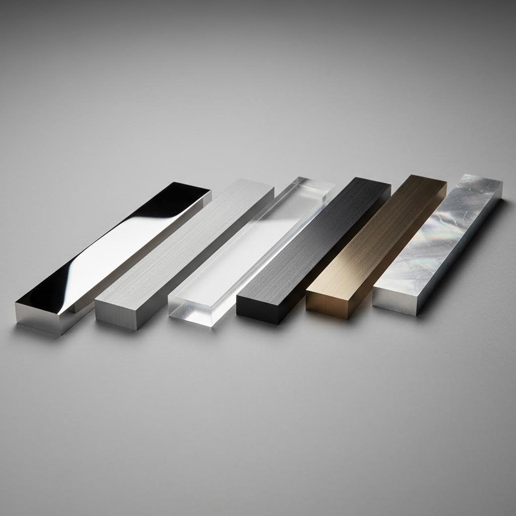
Here's a question that trips up even experienced designers: which aluminum alloy should you specify for your extruded aluminum profile? It's tempting to focus solely on strength numbers, but that approach misses the bigger picture. Your alloy choice ripples through every aspect of your project—from how easily your profile extrudes to what surface finishes you can achieve to how your finished parts perform in service.
Among the many aluminium extrusion types available, the 6000 series dominates the extrusion landscape. These alloys combine silicon and magnesium as their primary alloying elements, delivering an excellent balance of strength, corrosion resistance, and workability. But within this series, meaningful differences exist that directly impact your design decisions.
When designers debate aluminum extrusion alloys, the conversation almost always centers on 6063 versus 6061. Both belong to the same alloy family, share similar compositions, and work well for extrusion—yet they serve distinctly different purposes.
6063 aluminum is the workhorse of architectural and thin-wall applications. According to Howard Precision Metals, this alloy's popularity stems from its exceptional extrudability and anodizing responsiveness. It flows smoothly through complex die geometries, produces excellent surface finishes, and accepts acid etching beautifully for matte appearances. When polished, 6063 yields a highly reflective surface that can be enhanced through bright dip anodization.
The tradeoff? 6063 offers medium strength compared to other aluminum alloys. It's perfectly adequate for window frames, door systems, furniture, and decorative trim—but falls short when structural demands increase.
6061 aluminum steps in when strength becomes the primary concern. This precipitation-hardened alloy undergoes heat treatment that enhances its grain structure, resulting in superior durability. You'll find 6061 in automobiles, aircraft components, bicycle frames, camera lenses, and hydraulic manifolds—applications where material strength directly impacts safety and performance.
Here's the decision framework that actually works:
Beyond the 6063/6061 comparison, 6005 (and its variant 6005A) occupies valuable middle ground. This alloy offers higher strength than 6063 while maintaining better extrudability than 6061—making it popular for structural applications that don't quite demand 6061's full capabilities.
When evaluating aluminum profile extrusion options, consider these decision criteria rather than just comparing property lists:
| Alloy | Strength Rating | Extrudability | Surface Quality | Best Applications |
|---|---|---|---|---|
| 6063 | Medium (21-27 ksi yield) | Excellent—flows easily through complex dies | Exceptional—ideal for anodizing, polishing, and decorative finishes | Architectural trim, window frames, furniture, thin-wall tubing, decorative components |
| 6005/6005A | Medium-High (25-35 ksi yield) | Good—handles moderate complexity well | Good—suitable for most finishing requirements | Structural framing, transportation, ladder rails, platforms requiring moderate strength |
| 6061 | High (35-40 ksi yield) | Moderate—requires simpler profiles for best results | Good—acceptable for most applications but not optimal for decorative anodizing | Aircraft parts, automotive structures, bicycle frames, machine components, hydraulic manifolds |
Notice how extrudability and strength move in opposite directions? This isn't coincidental. The same alloying elements that boost strength—particularly increased silicon, magnesium, and copper content—also make the material more resistant to flow through the die. As A-Line Automation notes, understanding your project requirements thoroughly helps you strike the right balance between performance and manufacturability.
Weldability presents another consideration. Both 6063 and 6061 are weldable, typically through tungsten inert gas (TIG) welding. However, welding often reduces strength by as much as 30% in the heat-affected zone. Heat treatment can restore much of this strength, but you'll need to factor post-weld processing into your manufacturing plan if welded joints are critical.
Your alloy selection directly determines which surface treatments will look best on your extruded aluminum profiles. This connection catches many designers off guard—they specify an alloy for its mechanical properties, then discover their preferred finish won't work.
For anodizing, alloy composition matters enormously. According to the Aluminum Anodizers Council, clear anodize finishes show off the silver-gray metallic properties of aluminum, but the specific appearance varies by alloy. 6063's lower alloying content produces cleaner, more consistent anodized surfaces—particularly important for architectural applications where appearance uniformity across multiple pieces is essential.
The anodizing options available for your extruded aluminum profile include:
Powder coating offers more alloy flexibility than anodizing. Because powder coating builds up an applied layer rather than modifying the aluminum surface, substrate alloy has less impact on final appearance. However, surface quality still matters—profiles with die lines or surface imperfections will telegraph through powder coat finishes.
PVDF (polyvinylidene fluoride) coatings, commonly used in architectural applications for their exceptional weatherability, follow similar logic. The coating itself provides color and protection, but underlying surface quality affects the finished appearance.
When your project requires specific aesthetic outcomes, discuss alloy options with your manufacturer early. An experienced aluminum profile extrusion partner can guide you toward aluminium extrusion types that balance your mechanical requirements with your surface finish goals—avoiding costly surprises when profiles reach the finishing stage.
With your alloy selected and surface treatment strategy defined, the next step involves applying design-for-manufacturability principles that optimize your profile for efficient, cost-effective production.
You've locked in your dimensions and selected your alloy—but here's where theory meets reality. Your aluminum extrusion design guide isn't complete until you've considered how every detail affects the manufacturing process itself. The principles of design for manufacturability (DFM) transform good designs into great ones by ensuring your profile not only meets performance requirements but also extrudes efficiently, consistently, and economically.
Think of it this way: every design decision you make either helps or hinders the aluminum extrusion die. And since that die directly determines your production costs, cycle times, and part quality, getting DFM right pays dividends throughout your project's lifecycle.
The aluminum extrusion die represents a significant upfront investment—and how long it lasts depends almost entirely on your profile design. According to a comprehensive study of 616 die failures, design-related stress concentrations account for a substantial percentage of premature die replacements. Smart design choices can extend die life dramatically, spreading that tooling cost across more parts.
What kills dies prematurely? Sharp internal corners, extreme tongue ratios, and unbalanced metal flow patterns top the list. Each of these creates stress concentrations where the die steel fatigues and eventually cracks. Here's how to protect your tooling investment:
Die complexity also affects extrusion speed—and speed directly impacts your per-part cost. Simpler profiles with balanced metal flow extrude faster because the press can push material through more aggressively without risking defects. Complex hollow sections with multiple voids require slower speeds to maintain quality, adding cost to every foot produced.
Imagine pushing toothpaste through an off-center opening—the paste curves toward the side with less resistance. Aluminum behaves similarly during extrusion. Asymmetric profiles create uneven metal flow, causing the extruded section to curve, twist, or bow as it exits the die.
Symmetric designs solve this problem by ensuring metal flows evenly across the entire profile cross-section. When that's not possible—and functional requirements often demand asymmetry—understanding how to compensate becomes critical.
The Aluminum Extruders Council emphasizes these symmetry-related best practices:
Heat dissipation considerations tie directly into symmetry principles. Thick sections retain heat longer than thin ones, so profiles with dramatic thickness variations cool unevenly. This uneven cooling causes internal stresses that manifest as warping or dimensional inconsistency. When designing extruded aluminum channel shapes or other profiles with varying thicknesses, use gradual transitions rather than abrupt steps to minimize thermal gradients.
Certain design choices reliably drive up manufacturing costs—yet designers repeat them project after project. Learning from extrusion examples that failed helps you avoid the same pitfalls.
Here's a prioritized checklist of aluminum extrusion design guidelines that directly impact your bottom line:
Beyond basic geometry, consider how functional features affect manufacturability. Screw bosses—those cylindrical or semi-cylindrical features designed to receive fasteners—require careful attention. According to the AEC Aluminum Extrusion Manual, well-designed screw bosses integrate seamlessly into profiles, while poorly designed ones create weak points or extrusion difficulties.
Snap-fit connections represent another feature category worth mastering. These self-locking joints eliminate fasteners and simplify assembly—but only when designed within extrusion process constraints. The flexing elements of a snap-fit joint must have sufficient material to withstand repeated assembly cycles without cracking, yet remain thin enough to flex properly during initial installation.
Integrated channels—whether for wiring, fluid flow, or structural purposes—demonstrate aluminum extrusion's ability to consolidate multiple functions into a single profile. These features can eliminate secondary machining operations entirely, but they require careful consideration of the hollow-versus-semi-hollow classification and associated die requirements.
The most cost-effective aluminum extrusion designs share a common trait: they were developed with manufacturing constraints in mind from the very first sketch—not retrofitted to fix problems discovered during production.
Standard aluminum extrusions—catalog profiles available from stock—offer a useful benchmark for evaluating custom designs. If your custom profile significantly exceeds the complexity of standard shapes without clear functional justification, revisit your design. Sometimes splitting a complex profile into two simpler pieces that join together delivers better results at lower cost.
With these manufacturability principles integrated into your design approach, you're ready to navigate the complete workflow from initial concept through production-ready specifications—including the critical collaboration with your extrusion manufacturing partner.
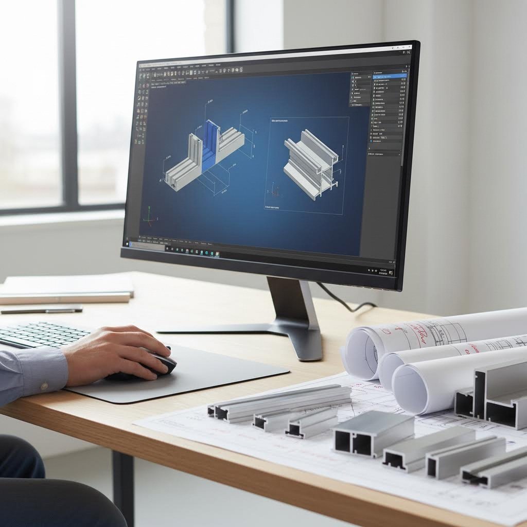
So you've mastered the principles—but how do you actually move from a rough idea to production-ready specifications? Here's what many guides get wrong: they present aluminum extrusion profile design as a straight line from concept to finished part. In reality, it's an iterative loop where each stage informs and refines the others. Understanding this workflow helps you avoid costly backtracking and ensures your extruded structural aluminum components meet both performance and manufacturing requirements.
Whether you're building with aluminum extrusion for the first time or refining an existing design, following a structured workflow keeps your project on track. Let's walk through each stage.
Every successful aluminum extrusion project starts with clearly defined requirements—not CAD drawings. Before opening your design software, answer these fundamental questions:
With requirements documented, feasibility assessment comes next. According to industry best practices, this stage determines whether your concept can be extruded economically—or needs fundamental rethinking. Key feasibility factors include circumscribing circle diameter (staying under 8 inches for optimal economics), wall thickness minimums for your chosen alloy, and tongue ratio limits for semi-hollow features.
Don't skip this step. A quick feasibility check with an experienced manufacturer can save weeks of design effort. Many extrusion suppliers offer preliminary design reviews at no cost—take advantage of this expertise before investing heavily in detailed drawings.
Here's where the iterative nature of profile design becomes apparent. Your initial concept almost never survives unchanged through production. Instead, expect multiple refinement cycles as you balance competing requirements.
The key stages of the design workflow typically include:
Each iteration should improve both performance and manufacturability. When you encounter conflicts—say, a thin tongue that improves assembly but threatens die life—document the tradeoffs explicitly. This record helps justify final design decisions and provides context if future modifications become necessary.
Prototype considerations deserve special attention. For aluminum extrusion projects, prototyping options range from machining profiles from solid stock (expensive but fast) to short extrusion runs using production dies (most representative but requires tooling investment). Your choice depends on what you're validating: if it's form and fit, machined prototypes work well. If you need to verify actual extrusion characteristics like surface finish and dimensional consistency, nothing substitutes for extruded samples.
Your CAD files serve as the primary communication vehicle with your extrusion manufacturer. Poor file preparation causes delays, misunderstandings, and costly errors. According to design process guidelines, common CAD file mistakes include overly complex drawings, unclear dimensioning, and missing critical specifications.
Follow these file preparation best practices to ensure smooth collaboration:
Beyond drawings, effective manufacturer communication includes context your files can't convey. Share information about your application, expected production volumes, assembly requirements, and any flexibility in specifications. This context helps manufacturers suggest optimizations you might not have considered.
For aluminum extrusion assembly applications, provide information about how your profile interfaces with other components. Knowing that your profile must mate with standard hardware, slide into specific tracks, or accommodate particular fastening methods helps manufacturers anticipate potential issues. If you're wondering how to cut aluminum extrusion after receiving parts, discuss cutting requirements upfront—some profiles benefit from specific cutting methods or end treatments.
The timing of manufacturer involvement matters enormously. Engaging your extrusion partner during conceptual design—not after detailed drawings are complete—yields the best results. Early collaboration catches manufacturability issues when they're easy to fix and often reveals opportunities for cost reduction or performance improvement that wouldn't surface otherwise.
Aluminum extrusion projects succeed when designers and manufacturers work as partners rather than sequential handoff points. With your design refined, files prepared, and manufacturer collaboration established, you're ready to address the surface treatment planning that often determines your profile's final appearance and performance.
Here's something that catches many designers off guard: the surface treatment you want on your finished aluminum angle or complex architectural section should influence your profile design from day one—not become an afterthought once extrusion is complete. Why? Because every coating and finishing process interacts differently with profile geometry, alloy composition, and dimensional tolerances.
Think about it this way. Your aluminum extrusion applications might demand a brilliant anodized finish for a storefront facade, a durable powder coat for industrial equipment, or a weatherproof PVDF coating for exterior cladding. Each finish has distinct requirements that affect how you design corners, specify tolerances, and select alloys. Getting these relationships right during the aluminium extrusion process—not after—prevents costly surprises and ensures your finished parts look exactly as intended.
Anodizing doesn't simply coat aluminum—it transforms the surface itself. During this electrochemical process, oxygen ions combine with the aluminum surface to create a thick, durable oxide layer. This layer becomes part of the metal rather than sitting on top of it. That fundamental difference has significant implications for your profile design.
According to research from AEC, the temper of each aluminum piece significantly impacts anodizing results. Studies examining AA6063 in T4, T5, T6, and T52 tempers show notable differences in appearance and color after both clear and electrolytically colored anodizing—even when using identical sulfuric acid processes.
Corner radii deserve particular attention when designing for anodized finishes. Sharp corners create visible sight lines in anodic coatings because the oxide layer builds up unevenly at geometric transitions. The effect becomes especially pronounced with colored anodizing, where thickness variations translate directly to color intensity differences. Specifying generous radii—1mm or larger when your application allows—produces more uniform coating appearance.
Surface geometry also affects etching behavior. During alkaline pretreatment, some grains etch deeper than others—a phenomenon called preferential grain etching (PGE). Research indicates that zinc, copper, and manganese concentrations in 6060 alloy, along with temper selection, influence PGE severity. These subtle surface variations become visible after anodizing, particularly on large flat surfaces viewed under uniform lighting.
The available anodizing options for your profiles include:
Unlike anodizing, powder coating and PVDF finishes build applied layers on top of your aluminum surface. This distinction offers more alloy flexibility—but surface quality and geometry still matter significantly.
Powder coating involves electrostatically charging finely powdered particles and spraying them onto the metal surface. According to finishing specialists, the charged particles adhere to the surface and are then heated, causing them to melt and form a protective, decorative coating. The result is highly durable and resistant to chipping, fading, and corrosion.
For powder coating success, your profile design should address these considerations:
PVDF (polyvinylidene fluoride) coatings represent the premium choice for architectural aluminum extrusion applications. As Sherwin-Williams notes, 70 percent PVDF resin-based coatings have become one of the most respected extrusion coatings available, delivering exceptional color retention and weathering resistance over decades of service.
PVDF finishes offer specific advantages:
Unlike coil coating where paint is applied before forming, aluminum extrusion creates the shape before finishing. This means your profile geometry must accommodate coating application equipment and processes. Discuss specific PVDF application requirements with both your extrusion manufacturer and coating applicator early in the design process.
Architectural projects increasingly demand profiles that combine multiple finish types—perhaps an anodized exterior surface paired with a powder-coated interior, or PVDF-finished sections adjacent to mill-finish structural areas. These multi-finish applications require thoughtful design decisions from the start.
Dimensional tolerance planning becomes critical when profiles receive different treatments on different surfaces. Anodizing adds material thickness (the oxide layer grows both into and out from the original surface), while powder coating adds applied thickness. A profile designed for tight mating with another component must account for these additions—and different finishes add different amounts.
Consider these design strategies for multi-finish success:
For architectural applications where aesthetic consistency across large installations matters, understanding how design choices affect finish uniformity becomes essential. Surface defects that seem invisible on mill-finish extrusions may become glaringly apparent after anodizing or coating. Research from Hydro Aluminium demonstrates that defects sometimes don't appear until surface treatment is applied—or even during end use—making root cause analysis extremely complex.
The bottom line? Surface treatment planning isn't a finishing step—it's a design step. The choices you make about corners, tolerances, alloys, and geometry during initial profile development directly determine what finishes are achievable and how your finished aluminum extrusion applications will look and perform.
With surface treatment requirements integrated into your design approach, the next critical consideration is ensuring your profile meets structural performance requirements—particularly when selecting profiles for load-bearing applications.
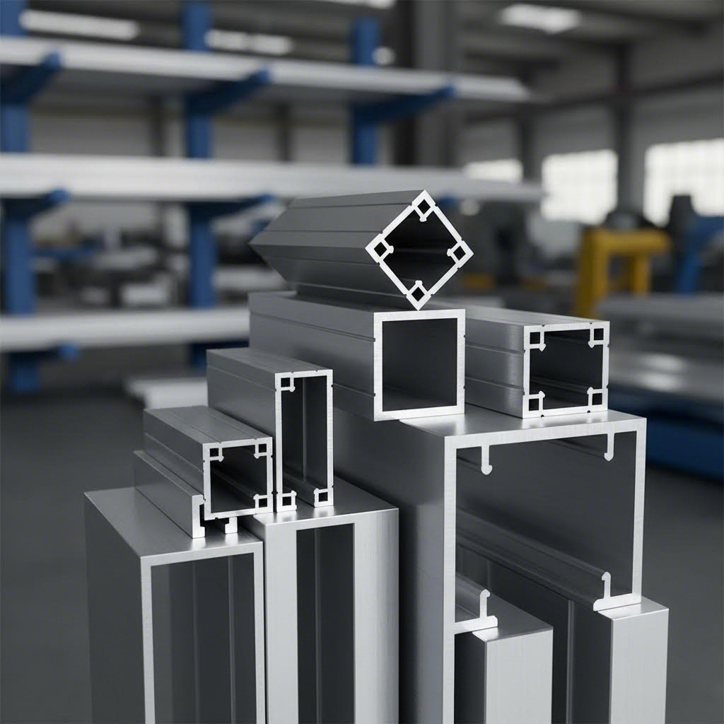
Your aluminum extrusion profile design might look perfect on paper—but will it actually support the loads your application demands? This is where many designers fall short. They focus on geometry and manufacturability while overlooking the structural analysis that determines whether their profile will perform safely under real-world conditions. Understanding how to evaluate and select structural aluminum extrusions separates competent designers from truly skilled engineers.
When you're building frames, supports, or load-bearing assemblies, profile selection becomes an engineering decision with measurable consequences. The wrong choice leads to excessive deflection, premature failure, or unnecessary weight and cost. The right choice? A structure that performs exactly as intended while using material efficiently.
Ever wonder why an aluminum square tube resists bending better than a solid bar of the same weight? The answer lies in a property called the area moment of inertia—often simply called "moment of inertia" or designated as I in engineering calculations.
Here's the intuitive explanation: moment of inertia measures how effectively a cross-section resists bending. Material located farther from the neutral axis (the center of bending) contributes more to bending resistance than material near the center. That's why hollow tubes outperform solid sections for bending applications—they concentrate material where it does the most good.
According to structural framing specialists, calculating bending moment requires understanding these extrusion-specific properties:
For aluminum tubing and structural profiles, manufacturers typically publish these values in their product documentation. When evaluating options, compare moment of inertia values about both the x-axis and y-axis—profiles often perform differently depending on loading orientation. A 2 square tubing profile, for example, has equal I values in both directions, making it ideal for applications where loading direction may vary.
Selecting the right profile is only half the equation—how you connect profiles and distribute loads determines whether your structure performs as calculated. This is where connection design becomes critical.
Traditional T-slot framing relies on friction-based joints that present a fundamental challenge: load capacity becomes unpredictable because joints can slip under stress. As engineering guides note, self-aligning connection systems using angled fasteners and high-strength brackets physically cannot slip out of alignment, making structural calculations more reliable.
When designing connections for structural aluminum extrusions, consider these load transfer principles:
Here's a practical tip from the AngleLock design guide: three-way corner brackets handle three profiles and a top plate simultaneously—eliminating multiple separate brackets, reducing weight, and creating stronger, more precise connections than friction-based alternatives.
Before investing in custom tooling, evaluate whether standard structural profiles can meet your requirements. The table below compares common profile types to help guide your selection:
| Profile Type | Bending Strength | Torsional Rigidity | Typical Structural Uses |
|---|---|---|---|
| T-Slot | Good—varies significantly by slot configuration and wall thickness | Moderate—open slots reduce torsional resistance | Machine frames, workstations, guarding, modular structures requiring reconfiguration |
| Channel (C/U) | Good about major axis; weak about minor axis | Low—open section twists readily under torsional loads | Framing, tracks, cable management, applications loaded primarily in one plane |
| Angle | Moderate—depends heavily on loading orientation relative to legs | Low—open profile offers minimal twist resistance | Bracing, corner reinforcement, trim, light structural supports |
| Square/Rectangular Tube | Excellent—closed section with material distributed efficiently | Excellent—closed section resists twisting effectively | Primary structural frames, columns, beams, applications with multi-directional loading |
| Round Tube | Excellent—uniform properties in all bending directions | Excellent—optimal shape for torsional resistance | Handrails, roll cages, furniture, applications requiring omnidirectional strength |
Notice how closed sections—tubes and rectangular profiles—consistently outperform open sections for both bending and torsion? That's the moment of inertia principle in action. An aluminum square tube concentrates material at the corners where it contributes most to structural performance.
So when does custom design make sense? Consider custom profiles when:
According to material comparison studies, aluminum's strength-to-weight ratio exceeds 2x that of mild steel—meaning properly designed aluminum structures can replace heavier steel assemblies while maintaining equivalent performance. This advantage becomes even more pronounced when custom profiles are optimized for specific loading conditions rather than using general-purpose standard shapes.
For applications where safety is paramount, include appropriate safety factors in your structural calculations. Self-aligning aluminum framing systems, with their predictable connection behavior, enable more accurate Finite Element Analysis (FEA) than friction-based alternatives with variable joint characteristics. This predictability helps ensure your frame can handle real-world use—not just theoretical calculations.
With structural requirements understood and profile selection complete, you're ready to bring your design to production—partnering with a manufacturer who can transform your specifications into finished aluminum extrusions.
You've traveled the complete journey—from understanding what is aluminum extrusions at their core to mastering dimensional parameters, alloy selection, manufacturability principles, and structural analysis. Now comes the moment that transforms all that knowledge into tangible results. The difference between a design that stays on paper and one that becomes a successful production run often comes down to two factors: having a clear action plan and partnering with the right manufacturer.
Let's crystallize everything you've learned into actionable next steps that move your aluminum extrusion profile design from concept to reality.
Before reaching out to manufacturers, ensure your design foundation is solid. The aluminum extrusion definition encompasses far more than just pushing metal through a die—it represents a complete engineering discipline where every decision interconnects. Review your design against these critical success factors:
The most successful aluminum extrusion designs are developed with manufacturing constraints in mind from the very first sketch—not retrofitted to fix problems discovered during production.
This principle, more than any other, separates projects that run smoothly from those plagued by delays and cost overruns. When you define aluminum extrusion requirements early and design within process capabilities from the start, you create parts that extrude efficiently, meet performance requirements, and stay within budget.
Your design checklist should confirm:
Even the best design requires a capable manufacturing partner to become reality. According to industry specialists, the depth of expertise and accumulated experience are undeniable hallmarks of leading custom aluminum extrusion manufacturers. Those with long-standing presence in the industry have navigated countless challenges, positioning them ideally to support your specific project needs.
When evaluating potential partners, look for manufacturers offering end-to-end capabilities. In-house die development, extrusion, secondary machining, and surface finishing under one roof ensures consistent quality control and streamlined communication. Outsourcing these operations across multiple suppliers introduces variability and complicates troubleshooting when issues arise.
As an example of comprehensive manufacturing capability, Shengxin Aluminium demonstrates what to look for in a production partner. With over 30 years of industry experience, their facility houses 35 advanced extrusion presses ranging from 600T to 5500T capacity—enabling them to handle everything from delicate architectural trim to heavy structural sections. Their CNC machining centers provide precise cutting, drilling, and bending to meet exact specifications, while extensive surface treatment options including custom anodizing colors (champagne, rose gold, and more), powder coating, PVDF, and micro-arc oxidation ensure your aluminum extrusions achieve the exact appearance and performance characteristics your application demands.
Key partnership criteria to evaluate include:
Ready to move forward? Here are your action items for transforming your profile design into production-ready aluminum extrusions:
Understanding what are aluminum extrusions used for across industries—from architectural facades to aerospace components—reveals the remarkable versatility of this manufacturing process. Your project joins a long tradition of engineers and designers who've leveraged extrusion aluminum to create products that combine strength, precision, and cost-effectiveness.
The journey from initial concept to finished production parts requires both technical knowledge and the right partnerships. You now have the foundational understanding to design profiles that extrude successfully, perform reliably, and meet your project's aesthetic and functional requirements. The next step? Put that knowledge into action with a manufacturing partner equipped to bring your vision to life.
Successful aluminum extrusion design requires attention to several critical factors. Maintain uniform wall thickness with adjacent-wall ratios under 2:1 to ensure even metal flow. Always specify corner radii of at least 0.5mm to extend die life and improve surface quality. Keep circumscribing circle diameters between 1-8 inches for optimal manufacturing economics. Design symmetric or balanced profiles whenever possible to prevent warping during extrusion. Additionally, engage with your extrusion manufacturer early in the design process to identify potential issues before die fabrication begins.
Solid profiles have no enclosed voids and use simple flat-face dies, making them the most cost-effective option with fastest extrusion speeds. Hollow profiles contain fully enclosed voids like rectangular or round tubes, requiring more complex porthole dies with mandrel and cap assemblies. Semi-hollow profiles have partially enclosed voids with gaps, classified by their tongue ratio (Area/Gap²). Higher tongue ratios increase die stress and manufacturing complexity. Your choice depends on balancing structural requirements, die costs, and production economics.
Choose 6063 aluminum when surface appearance matters most, as it offers exceptional extrudability and produces excellent anodized finishes. It works well for thin-walled architectural profiles, window frames, and decorative applications. Select 6061 when structural strength is paramount—it delivers higher yield strength (35-40 ksi versus 21-27 ksi for 6063) and suits aircraft components, automotive structures, and heavy-duty applications. However, 6061 requires simpler profile geometries and doesn't anodize as uniformly as 6063.
Standard cross-sectional tolerances vary by dimension size. For dimensions up to 0.124 inches, expect ±0.006 inches standard tolerance. Dimensions between 0.500-0.749 inches allow ±0.009 inches, while 1.000-1.499 inch dimensions permit ±0.012 inches. Precision tolerances run approximately 30% tighter but cost more due to slower extrusion speeds and increased inspection. Wall thickness tolerances for hollow profiles range from 10-15% of specified dimension. Standard straightness tolerance is 0.0125 inches per foot of length.
Surface treatments significantly influence design decisions from the start. For anodizing, specify generous corner radii (1mm or larger) to achieve uniform coating appearance, and select 6063 alloy for best results. Powder coating requires accessible surfaces for pretreatment and builds thicker on external corners. PVDF coatings offer exceptional weatherability for architectural applications but require coordination between extrusion and coating specialists. When combining multiple finishes on one profile, design natural masking breaks and allow for coating thickness buildup on mating surfaces.



 خدمة الإنترنت
 0086 136 3563 2360
 sales@sxalu.com
 +86 136 3563 2360
 العربية
 English
 français
 Deutsch
 русский
 español
 português
 ไทย
ไทย Việt
Việt Українська