
When your extruded aluminum component doesn't fit during assembly, the root cause often traces back to one overlooked factor: tolerances. These specifications determine whether your parts snap together seamlessly or require costly rework. Yet many engineers specify aluminum extrusion tolerances without fully understanding the variables that control them—leading to rejected parts, budget overruns, and project delays.
Imagine ordering a custom aluminum profile expecting a wall thickness of 3mm, only to receive parts measuring 3.2mm. Is that acceptable? The answer depends entirely on your tolerance specification. By aluminum extrusion definition, tolerances are the guidelines that define allowable deviations from specified dimensions within which extruded parts must fall to be considered acceptable.
Aluminum extrusion tolerances are the permissible range of dimensional variation from nominal specifications that determines whether an extruded profile meets quality requirements for its intended application.
These parameters serve as the boundaries within which extruders must operate to ensure parts function as intended without requiring additional modifications. When you specify aluminum extrusion dimensions on a drawing, you're not just defining ideal measurements—you're establishing the acceptable range that balances manufacturing capabilities with functional requirements.
You might wonder: why obsess over fractions of a millimeter? The stakes become clear when you consider real-world applications. Precision aluminum extrusion directly impacts three critical outcomes:
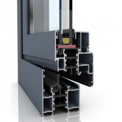
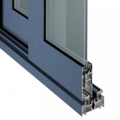
Consider heat sinks where flatness tolerances ensure uniform contact for efficient thermal transfer. Or window frames where angular precision guarantees tight seals. In each case, the tolerance specification isn't arbitrary—it's engineered to match application requirements.
Here's what most tolerance guides fail to explain: your achievable tolerances depend heavily on your profile's circumscribing circle diameter (CCD). This measurement represents the diameter of the smallest circle that will entirely enclose your extrusion's cross-section.
Why does CCD matter so much? According to the Aluminum Extruders Council, this dimension directly affects the economics and precision capabilities of your extrusion. Most common aluminum extrusion sizes fall within a CCD between one and ten inches, with profiles under 8 inches offering the most cost-effective production. Larger CCDs—some extruders handle profiles up to 32 inches—come with proportionally wider tolerance ranges due to increased material flow complexity and cooling variations.
Several additional factors influence your achievable tolerances:
Understanding these relationships transforms tolerance specification from guesswork into informed engineering. Throughout this guide, you'll learn how to apply industry standards, interpret tolerance tables, and communicate requirements effectively—bridging the gap between raw tolerance data and practical application knowledge that delivers results.

So you understand what tolerances are and why they matter—but where do the actual numbers come from? Unlike arbitrary manufacturer specifications, aluminum extrusion tolerances follow carefully developed industry standards. These standards weren't created overnight. Technical committees from both The Aluminum Association and the American National Standards Institute collaborated to establish guidelines that balance extruder manufacturing capabilities with designer requirements.
Navigating these standards can feel overwhelming at first. Multiple documents, overlapping specifications, and cross-references between publications create confusion for engineers who simply need to specify tolerances correctly. Let's break down the three key standards you need to know and how they work together.
When engineers reference "standard tolerances" for aluminum extrusions, they're typically pointing to ANSI H35.2. This document serves as the primary dimensional tolerance standard for aluminum mill products in the United States. Published as the National Standard Dimensional Tolerances for Aluminum Mill Products, it provides the specific dimensions and tolerance values that govern everything from wall thickness to straightness.
What makes ANSI H35.2 particularly valuable is its practical structure. The standard features tolerance values organized in table format, with formulas that account for the varying degrees of difficulty extruders face when controlling different tolerance dimensions. You'll find specifications that correlate directly with:
The standard recognizes that not all dimensions present equal manufacturing challenges. Angular tolerances, flatness requirements, and straightness specifications each receive dedicated treatment based on real-world extrusion process constraints.
While ANSI H35.2 focuses on dimensional tolerances, ASTM B221 addresses the material itself. This specification covers aluminum and aluminum-alloy extruded bars, rods, wire, profiles, and tubes. Think of it as the companion document that ensures the material you're extruding can actually achieve the tolerances you're specifying.
ASTM B221 defines critical parameters including:
Why does this matter for tolerances? Different alloys behave differently during extrusion. A 6061-T6 profile will hold tolerances differently than a 2024-T4 profile due to variations in flow characteristics, extrusion temperatures, and cooling behavior. The aluminum association standards in ASTM B221 ensure you're selecting materials compatible with your tolerance requirements.
If ANSI H35.2 and ASTM B221 seem like separate puzzle pieces, the Aluminum Association's Aluminum Standards and Data (ASD) publication brings everything together. This comprehensive reference consolidates tolerance tables, alloy specifications, and design guidelines into a single resource that engineers can rely on for day-to-day specification work.
The ASD publication includes:
Updated regularly—with the 2024 edition being the current standard—the ASD serves as the authoritative source when disputes arise or clarification is needed. Rather than hunting through multiple documents, experienced engineers keep this reference within arm's reach.
Here's the key insight: these standards work as an integrated framework. ASTM B221 defines what you're extruding, ANSI H35.2 establishes how precisely it can be made, and the ASD publication provides the practical tools for applying both. Understanding this relationship prevents the common mistake of specifying tolerances that are technically impossible for your chosen alloy—or paying premium prices for precision levels your application doesn't actually require. With this foundation in place, you're ready to explore the specific tolerance categories and when each applies.
Now that you understand the standards framework, here's where many engineers stumble: not all tolerances are created equal. When specifying requirements for standard aluminum extrusions, you're actually choosing between distinct tolerance grades—each with different capabilities, applications, and cost implications. Confusing these categories leads to either overspending on unnecessary precision or underspecifying requirements that cause assembly failures.
Let's clear up the confusion by examining the three main tolerance categories and understanding exactly when each applies to your aluminum extrusion design.
Think of tolerance grades as tiers of manufacturing precision. Each tier represents a different balance between dimensional accuracy and production economics. Here's what separates them:
Standard (Commercial) Tolerances: These represent the default specifications that any qualified extruder can achieve using conventional equipment and processes. When you order standard aluminum extrusion profiles without specifying tighter requirements, you'll receive parts manufactured to these baseline parameters. They're perfectly suitable for structural applications, general framing, and situations where exact dimensions aren't critical to function.
Precision Tolerances: When your application demands tighter control—perhaps for sliding mechanisms, mating assemblies, or aesthetic consistency—precision tolerances cut the allowable deviation significantly. Achieving these specifications requires more careful process control, additional quality inspection, and often slower production speeds.
Special Tolerances: Sometimes even precision grades aren't tight enough. Special tolerances represent custom specifications negotiated directly with your extruder for unique applications. These might apply to aerospace components, medical devices, or high-precision instruments where standard aluminium extrusions simply won't meet functional requirements.
| Tolerance Type | Typical Deviation Range | Common Applications | Relative Cost Impact |
|---|---|---|---|
| Standard (Commercial) | Baseline per ANSI H35.2 | Structural frames, architectural trim, general enclosures | Lowest cost |
| Precision | Approximately 50% of standard | Sliding assemblies, mating components, visible surfaces | 15-30% premium |
| Special | Negotiated case-by-case | Aerospace, medical, high-precision instruments | 40%+ premium; may require custom tooling |
The cost implications deserve careful consideration. Specifying precision tolerances when standard would suffice doesn't just increase your per-piece price—it may limit your supplier options, extend lead times, and require more rigorous incoming inspection on your end. Conversely, under-specifying tolerances for profile aluminum extrusion that requires tight fits creates expensive downstream problems during assembly.
Dimensional tolerances govern the measurable features of your extrusion's cross-section. These are the specifications you'll reference most frequently when designing parts that must fit together or interface with other components. Key dimensional tolerance categories include:
Each dimensional tolerance in your specification should tie directly to a functional requirement. Ask yourself: what happens if this dimension falls at the extreme end of its tolerance range? If the answer is "nothing significant," you may be overspecifying. If the answer involves interference, gaps, or performance degradation, your tolerance is appropriately tight.
While dimensional tolerances address the cross-section, geometric tolerances control how that cross-section behaves along the extrusion's length. These specifications become increasingly important as your parts get longer or when surface contact matters for your application.
The four primary geometric tolerances you'll encounter are:
Geometric tolerances often cause more assembly problems than dimensional ones—yet they're frequently overlooked during specification. Imagine a perfectly dimensioned extrusion that twists 2 degrees over its length. Cross-sectional measurements pass inspection, but the part won't fit your application. Always consider both tolerance categories when developing your specifications.
Understanding these tolerance types gives you the vocabulary to communicate precisely with suppliers and the framework to make informed trade-offs. But how do these tolerances change based on your profile's shape and complexity? That's exactly what we'll explore next.
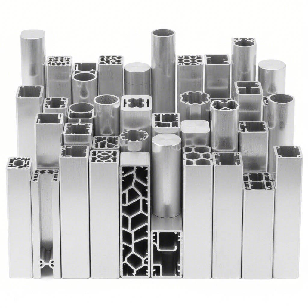
You've selected your tolerance grade—but here's what catches many engineers off guard: the same tolerance specification produces different results depending on your profile's geometry. A solid bar, an aluminum extrusion tube, and a complex semi-hollow shape each present distinct manufacturing challenges that directly affect achievable dimensional accuracy.
Why does shape matter so much? During extrusion, molten aluminum flows through a die under tremendous pressure. The path that material takes—whether filling a simple solid shape or navigating around mandrels to create hollow voids—determines how consistently the final dimensions match your specifications. Understanding these relationships helps you set realistic expectations and avoid specifying tolerances your profile geometry simply cannot achieve.
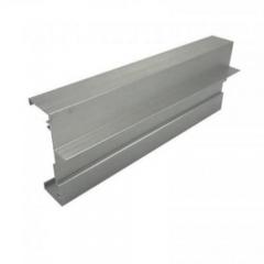
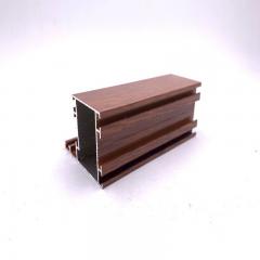
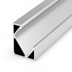
Solid profiles represent the most straightforward extrusion geometry. Think of square aluminum extrusion bars, rectangular channels, and aluminum t bar extrusion shapes without enclosed voids. Because material flows directly through a single-piece die without navigating around internal supports, these profiles typically achieve the tightest tolerances with the least manufacturing complexity.
Key tolerance factors for solid profiles include:
According to Keymark's tolerance reference, the standard and precision tolerances in Table 11.2 apply to average profiles, but aggressive geometric characteristics may require wider tolerances even for seemingly simple solid shapes. When your solid profile features thin legs, sharp corners, or significant variations in wall thickness across its cross-section, expect tolerance capabilities to shift accordingly.
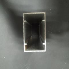
Hollow profiles—including aluminum tube profiles, rectangular tubes, and complex multi-void sections—introduce additional variables that affect tolerance capabilities. The die construction alone differs fundamentally: hollow shapes require porthole or bridge dies where aluminum flows around internal supports before welding back together to form the enclosed void.
This manufacturing complexity translates directly to tolerance considerations:
When specifying tolerances for aluminium extrusion tube products, pay particular attention to how your tolerance applies. Is the dimension specified between outside surfaces, inside surfaces, or as wall thickness itself? Each measurement method interacts differently with eccentricity tolerances, and misunderstanding this relationship causes frequent specification errors.
Beyond the solid-versus-hollow distinction, overall profile complexity plays a decisive role in tolerance capability. Semi-hollow profiles—those with partially enclosed voids that don't qualify as fully hollow—occupy a middle ground that requires careful tolerance consideration.
The circumscribing circle diameter (CCD) establishes the foundation for tolerance scaling. As the Aluminum Association tables indicate, larger profiles receive proportionally larger tolerance allowances. This isn't arbitrary—it reflects real manufacturing physics:
The relationship between complexity and tolerance extends to specific features within your profile. According to footnote guidance in the Aluminum Association standards, when a dimension comprises two or more component dimensions, the applicable tolerance equals the sum of the component tolerances—if all components are individually indicated. This tolerance stack-up effect means complex profiles with many interrelated dimensions accumulate tolerance ranges faster than simple shapes.
What does this mean practically? If you're designing a profile with multiple chambers, thin walls connecting thicker sections, or asymmetric geometry, your tolerance expectations should adjust accordingly. The same precision tolerance that's readily achievable on a simple solid bar may require special negotiation—and premium pricing—on a complex multi-void aluminum tube extrusion.
With profile geometry's influence on tolerances now clear, the next step is learning how to actually read and apply the tolerance tables that govern your specifications.
You've got the standards, you understand profile types—now comes the practical challenge that trips up even experienced engineers: actually using tolerance tables correctly. These tables pack tremendous information into compact formats, but their footnotes, exceptions, and cross-references contain critical details that determine whether your specification works in practice or fails during production.
According to the Aluminum Extruders Council, standard dimensional tolerances for extrusion are explained with illustrated examples in the Extrusion Manual, with additional data available through the Aluminum Association. But having access to these resources is only half the battle—interpreting them correctly separates successful projects from costly specification errors.
When you first open an aluminum extrusion design guide, the tolerance tables can seem overwhelming. Rows of numbers, multiple columns, and cryptic footnote symbols create an intimidating first impression. Here's how to navigate them systematically:
Start with your CCD. Locate the row corresponding to your profile's circumscribing circle diameter. This establishes the baseline tolerance range for your specific profile size. Remember—larger CCDs mean proportionally larger allowable deviations.
Identify the dimension type. Tolerance tables separate specifications by feature category. You'll typically find distinct columns or sections for:
Check the applicable tolerance class. Tables often present both standard and precision values side by side. Verify you're reading the correct column for your specification requirements before pulling numbers.
Sounds straightforward? Here's where many engineers stumble: they grab a tolerance value without checking the footnotes. Those small superscript numbers reference exceptions, special conditions, and application limitations that fundamentally change how the tolerance applies. A footnote might indicate that your dimension requires the sum of two component tolerances, that a minimum radius affects the applicable specification, or that certain alloys require adjusted values.
Cross-sectional tolerances get most of the attention, but length and straightness specifications often cause more real-world problems. Why? Because these tolerances compound over distance, and longer extrusions magnify small deviations into significant assembly issues.
Length tolerances specify how much your cut-to-length extrusion can deviate from the nominal dimension. These typically follow a formula based on the specified length, with longer pieces receiving proportionally larger allowances. When ordering extruded aluminum shapes from any catalog, pay attention to whether length tolerance is specified as plus-only, minus-only, or bilateral—this affects how you dimension mating parts.
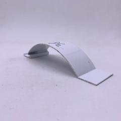
Straightness tolerances define the maximum deviation from a true straight line over a given length. The Mid-States Aluminum reference emphasizes a critical question: "How straight is straight enough?" The answer depends entirely on your application. A structural frame member might tolerate significantly more bow than a precision slide rail, even though both might start from the same tolerance table.
Standard straightness specifications typically express deviation as inches per foot of length. For example, a 0.012 inch per foot straightness tolerance means a 10-foot extrusion could deviate up to 0.12 inches from perfectly straight while still meeting specification. This cumulative effect catches designers who focus only on short sample measurements during incoming inspection.
When your application requires tighter straightness than standard aluminium extrusion design guidelines permit, you have options: specify precision tolerances, plan for post-extrusion straightening operations, or design your assembly to accommodate the expected deviation. Each approach carries different cost and schedule implications.
Individual tolerances rarely exist in isolation. When multiple extruded components assemble together—or when a single complex profile contains interrelated dimensions—tolerance stack-up becomes your primary concern. This is where theoretical specifications meet practical assembly reality.
Consider a simple example: you're designing a frame using four aluminum extrusions that must form a precise rectangle. Each piece has its own length tolerance, straightness tolerance, and cross-sectional dimensional tolerances. If every piece falls at the extreme end of its allowable range—all in the same direction—your frame might not close properly. Worse, it might close but with internal stresses that cause problems over time.
Effective stack-up management requires these strategies:
The footnotes in tolerance tables often address stack-up directly. When a dimension comprises multiple component dimensions, the applicable tolerance typically equals the sum of those component tolerances—if each component is individually specified on your drawing. Missing this detail leads to unrealistic expectations about assembled accuracy.
One final consideration: secondary processing affects your tolerance budget. If your extrusions will undergo CNC machining, anodizing, or powder coating, account for material removal or addition in your stack-up calculations. A profile that meets dimensional tolerance as-extruded might fall outside specification after a 0.001-inch anodize layer adds to all surfaces.
With tolerance tables now demystified, you're ready to explore how different industries apply these specifications—and why aerospace, automotive, and architectural applications each demand distinct approaches to tolerance specification.
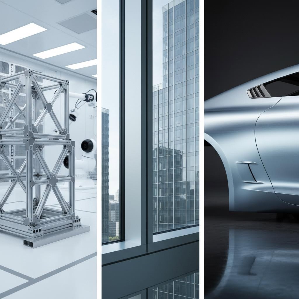
Here's a reality that tolerance tables don't fully capture: the same aluminum extrusion meeting identical dimensional specifications might pass inspection for one industry while failing completely for another. Why? Because different sectors layer additional requirements on top of baseline standards—and these industry-specific expectations fundamentally shape how you should approach tolerance specification.
Understanding these distinctions prevents two costly mistakes. First, overspecifying tolerances for applications that don't require aerospace-level precision wastes money and limits supplier options. Second, underspecifying for demanding applications creates downstream failures that far exceed any upfront savings. Let's examine how three major sectors—aerospace, automotive, and architectural—approach tolerance requirements differently.
When lives depend on component performance, tolerance requirements tighten dramatically. Aerospace applications reference AMS-QQ-A specifications (Aerospace Material Specifications) that impose stricter requirements than commercial standards. Documents like AMS-QQ-A-200/3 for 6061 alloy and AMS-QQ-A-225/8 for 7075 alloy don't just specify material properties—they establish tolerance expectations that exceed standard ANSI H35.2 values.
What makes aerospace tolerance requirements distinct?
The cost implications are significant. Aerospace-grade extrusions typically command premiums of 40% or more compared to commercial equivalents—and lead times extend accordingly. However, attempting to substitute commercial tolerances in aerospace applications risks catastrophic failure modes that no cost savings can justify.
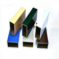
Shift from aircraft to buildings, and tolerance priorities change completely. Architectural aluminum extrusions prioritize visual consistency, weather sealing, and assembly efficiency over the absolute dimensional precision aerospace demands. When you're building with aluminum extrusion for curtain walls, storefronts, or window systems, different factors drive your tolerance decisions.
Architectural applications typically accept standard commercial tolerances because:
That said, architectural applications aren't tolerance-free zones. Critical dimensions like glass rabbet depths, thermal break alignment, and hardware mounting locations still require careful specification. The difference lies in identifying which dimensions truly matter for function and appearance versus which can accept standard commercial variation.
Your extrusion tolerance story doesn't end when profiles leave the press. Downstream operations—CNC machining, surface finishing, welding, and assembly—each interact with your as-extruded tolerances in ways that demand advance planning.
CNC Machining Considerations: If your extrusions will undergo precision machining, the as-extruded tolerance affects how much material you must remove to achieve final dimensions. Tighter extrusion tolerances reduce machining time and stock removal, but the cost trade-off depends on volumes and machining complexity.
Surface Finishing Effects: Anodizing adds 0.0002" to 0.001" per surface depending on coating thickness. Powder coating adds more. These additions must factor into your tolerance calculations, especially for mating surfaces or close-fit assemblies.
Assembly Operations: Welded assemblies accumulate distortion that can exceed original extrusion tolerances. Planning for post-weld straightening or designing weld sequences to minimize distortion often proves more effective than specifying tighter incoming tolerances.
| Industry Sector | Typical Tolerance Grade | Governing Specifications | Key Tolerance Priorities | Secondary Process Considerations |
|---|---|---|---|---|
| Aerospace/Defense | Precision to Special | AMS-QQ-A-200/3, AMS-QQ-A-225/8 | Dimensional accuracy, traceability, fatigue life | Precision machining, chemical conversion coating |
| Automotive | Standard to Precision | OEM specifications, IATF 16949 | Repeatability, crash performance, assembly fit | Robotic welding, e-coating, high-volume machining |
| Architectural | Standard (Commercial) | AAMA specifications, local building codes | Visual consistency, weather sealing, installation ease | Anodizing, powder coating, field cutting |
Automotive applications occupy interesting middle ground. High-volume production demands repeatability—not necessarily the tightest tolerances, but consistent tolerances that allow automated assembly without adjustment. Structural aluminium extrusions in crash structures must meet specific dimensional requirements for predictable energy absorption, while interior trim pieces prioritize visual consistency over absolute precision.
The key insight across all industries: tolerance specification should flow backward from end-use requirements, not forward from manufacturing convenience. Start by identifying what your application truly demands, then select the tolerance grade that reliably delivers that performance without unnecessary cost. With industry requirements clarified, the next consideration is understanding what drives tolerance costs—and how to optimize your specifications for both performance and budget.
You've specified your tolerances, selected the right industry standards, and understood profile geometry effects—but here's the question that ultimately determines project viability: can you afford those specifications? Tighter tolerances always sound better on paper, yet the cost implications cascade through every aspect of production. Understanding this relationship transforms tolerance specification from technical exercise into strategic decision-making.
The reality is straightforward: every incremental improvement in dimensional precision carries a price tag. Sometimes that investment pays off through reduced assembly problems and improved product performance. Other times, you're paying premium prices for precision your application doesn't actually require. Let's examine the true cost drivers and troubleshoot the tolerance problems that eat into your budget.
When you request precision tolerances on an extruded aluminum bar instead of accepting commercial specifications, you're triggering a chain of cost increases that extends far beyond the obvious. Here's what actually changes:
Consider aluminum bar extrusions as an example. A simple rectangular aluminum extrusion bar at commercial tolerances might run continuously for hours with minimal oversight. That same profile specified to precision tolerances could require operator intervention every few hundred feet to verify dimensions—dramatically changing the economics.
The cumulative impact? Precision tolerances typically add 15-30% to your per-piece cost compared to standard specifications. Special tolerances can exceed 40% premiums and may require dedicated die sets that amortize across your order alone. Before specifying tighter tolerances, ask yourself: does the downstream value justify this upstream investment?
When your aluminum extrusion bars arrive outside specification, finger-pointing begins. But understanding what actually causes tolerance problems helps you troubleshoot effectively—and sometimes reveals that the real solution lies in specification adjustment rather than manufacturing demands.
The primary sources of dimensional variation include:
Sounds like manufacturing is full of variables? It is. The extrusion process involves molten metal, extreme pressures, and complex thermal dynamics. Specifications that ignore these realities set up both designer and manufacturer for frustration. The most successful tolerance specifications acknowledge process variability while establishing boundaries that protect functional requirements.
Here's the good news: you often have more control over tolerance outcomes than you realize. Strategic design decisions can dramatically improve achievable tolerances without increasing costs—or can reduce costs while maintaining the precision you actually need.
Consider these manufacturability improvements:
Communication with your extruder during design development pays dividends. Experienced manufacturers can often suggest minor geometry modifications that dramatically improve tolerance capability without affecting your part's function. A slight radius increase here, a small wall thickness boost there—these adjustments might save you from special tolerance charges while delivering the dimensional performance you need.
The cost-tolerance relationship isn't fixed—it's negotiable through smart design choices. Engineers who understand this dynamic achieve better results at lower costs than those who simply specify tight tolerances and expect manufacturers to figure it out. With this economic framework in mind, you're ready to translate your tolerance requirements into effective supplier communication during the ordering process.

You've done the engineering work—understood your tolerance requirements, selected appropriate grades, and optimized your design for manufacturability. Now comes the moment where specifications meet reality: communicating those requirements to suppliers during the RFQ process. This step separates projects that flow smoothly into production from those that bog down in misunderstandings, requotes, and specification disputes.
The challenge? Many engineers assume that sending a drawing with tolerance callouts is sufficient. But as Alexandria Industries emphasizes, having discussions with your extruder during the design and quoting stage to agree on tight tolerance features is essential for mutual tolerance agreement and establishing tolerance hierarchy. Without this dialogue, you're gambling that your specifications align with what suppliers can actually deliver.
Your technical drawing serves as the legal contract between you and your supplier. Every tolerance callout, every dimension, every note carries weight when parts arrive for inspection. Getting this documentation right prevents costly disputes and ensures everyone works from the same expectations.
Start with these drawing essentials:
One common mistake deserves special attention: overloading drawings with tight tolerances on non-critical dimensions. According to manufacturing specialists, this is a major source of hidden costs. These tight tolerance features can result in requests for print deviations, longer setups, reruns, costly die trials, and unnecessary tooling alterations—all leading to price increases and delayed deliveries.
Before finalizing your drawing, ask yourself: does each tight tolerance callout directly affect form, fit, or function? If not, consider relaxing it to commercial standards. Some dimensions may not require explicit tolerances at all—just a visual inspection to ensure the part has its intended shape.
Not all extruders offer equal tolerance capabilities. Press capacity, die development expertise, process control systems, and quality infrastructure all influence what a manufacturer can reliably achieve. Evaluating these factors during supplier selection prevents the frustration of discovering capability gaps after you've committed to a vendor.
When assessing potential suppliers, investigate these capability indicators:
When comparing stock aluminium extrusion profiles to custom extrusions, remember that standard aluminum profiles from catalog offerings come with published tolerance specifications you can verify. Custom profiles require supplier capability discussions before you can confirm achievable tolerances.
For projects requiring tight tolerance control combined with secondary processing, suppliers offering end-to-end support from die development through mass production eliminate handoff issues between multiple vendors. Shengxin Aluminium's deep processing services exemplify this integrated approach, combining advanced extrusion capacity with precision CNC machining and comprehensive surface treatment options.
The most successful tolerance outcomes emerge from collaborative relationships, not adversarial specification enforcement. Treating your extruder as a partner rather than a commodity supplier unlocks expertise that improves both quality and cost-effectiveness.
Effective collaboration starts with these communication practices:
When reviewing quotes, look beyond price per piece. A supplier quoting slightly higher but committing to your tolerance requirements without deviation requests often delivers better total value than the lowest bidder who immediately pushes back on specifications.
Final drawings should reflect agreements reached during these discussions. As QS&T recommends, always provide manufacturers with the final version of your drawing rather than initial drafts. This prevents changes during production and ensures everyone works from the same approved specifications.
The tolerance specification process ultimately comes down to clear communication, realistic expectations, and mutual understanding between designer and manufacturer. Engineers who invest time in proper specification—and who partner with capable suppliers—consistently achieve better results than those who simply transmit drawings and hope for the best. Your extrusions will only be as precise as the communication that defines them.
Standard aluminum extrusion tolerances are defined by ANSI H35.2 and published in the Aluminum Association's Aluminum Standards and Data (ASD). These baseline specifications vary based on your profile's circumscribing circle diameter (CCD), with larger profiles receiving proportionally larger allowable deviations. For linear cross-section dimensions, typical standard tolerances are approximately ±0.008 inches per inch of dimension, while wall thickness tolerances generally run ±10% of the specified dimension. Precision tolerances cut these values roughly in half but add 15-30% to manufacturing costs.
Standard (commercial) tolerances represent default specifications any qualified extruder can achieve with conventional equipment, suitable for structural frames and general applications. Precision tolerances reduce allowable deviation by approximately 50%, requiring more careful process control, additional quality inspection, and slower production speeds. This tighter control is essential for sliding mechanisms, mating assemblies, and visible surfaces. The cost difference is significant—precision tolerances typically add 15-30% to per-piece costs, while special tolerances negotiated for aerospace or medical applications can exceed 40% premiums.
The circumscribing circle diameter—the smallest circle that entirely encloses your extrusion's cross-section—directly determines your achievable tolerances. Larger CCDs receive proportionally larger tolerance allowances because of increased thermal expansion effects during cooling, greater material flow distance from die center, higher die deflection under extrusion pressure, and increased susceptibility to distortion during handling. Most cost-effective production occurs with profiles under 8 inches CCD, though some extruders handle profiles up to 32 inches with appropriately adjusted tolerance expectations.
Three key standards work together: ANSI H35.2 serves as the primary dimensional tolerance standard for aluminum mill products, providing specific tolerance values in table format. ASTM B221 covers material specifications including alloy designations, temper conditions, and mechanical properties that affect tolerance capabilities. The Aluminum Association's Aluminum Standards and Data (ASD) publication consolidates both into a comprehensive reference with complete tolerance tables, alloy property data, and design formulas. Aerospace applications add AMS-QQ-A specifications for stricter requirements.
Start by explicitly referencing the governing standard (e.g., 'Tolerances per ANSI H35.2') on your technical drawing. Add specific tolerance callouts to critical dimensions affecting fit, function, or appearance rather than relying solely on title block tolerances. Establish clear datums to minimize process variation, and distinguish which features require precision versus commercial tolerances. Discuss tolerance hierarchy with your manufacturer during the design phase—suppliers like Shengxin Aluminium with 30+ years experience and integrated die development capabilities can provide valuable feedback on achievable specifications before production begins.


 خدمة الإنترنت
 0086 136 3563 2360
 sales@sxalu.com
 +86 136 3563 2360
 العربية
 English
 français
 Deutsch
 русский
 español
 português
 ไทย
ไทย Việt
Việt Українська