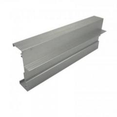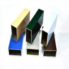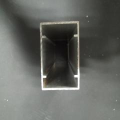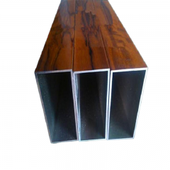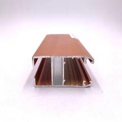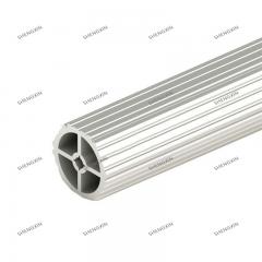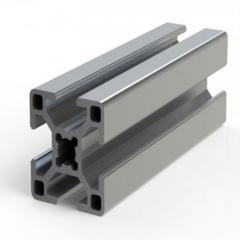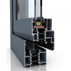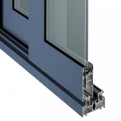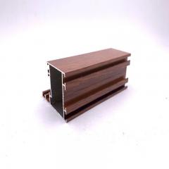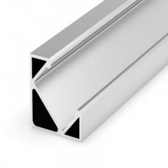
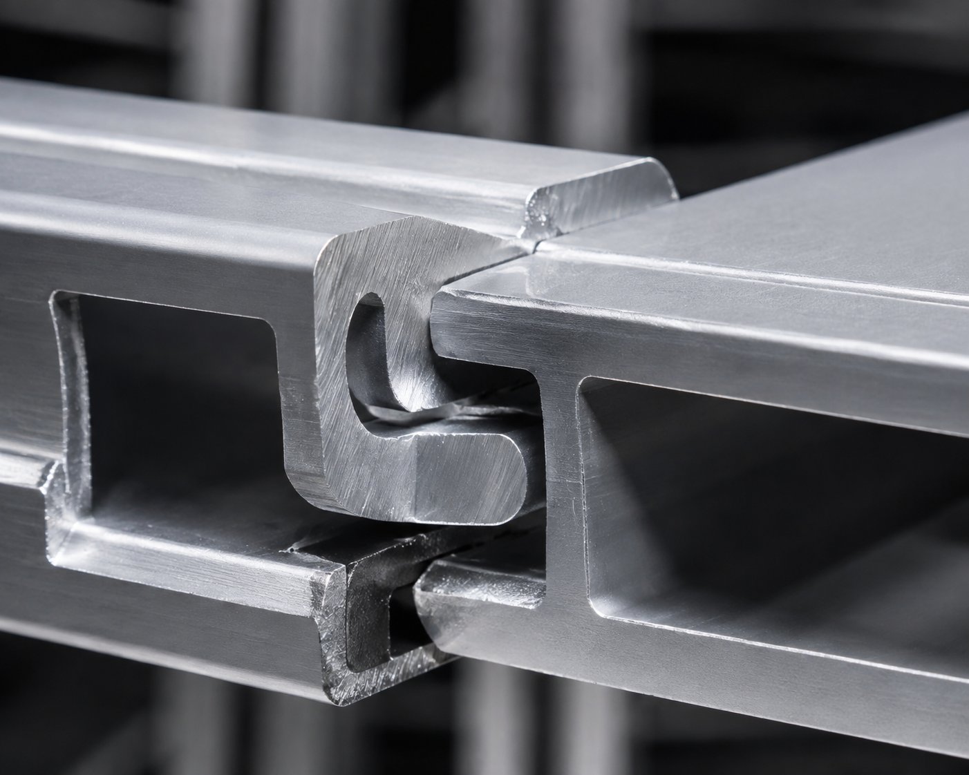
Have you ever wondered how aluminum profiles connect seamlessly without visible screws or bolts? The answer lies in interlocking aluminum extrusions—specialized extruded aluminum profiles engineered with complementary geometries that slide, snap, or rotate together to form secure connections.
Interlocking aluminum extrusions are custom-designed profiles featuring modified tongue-and-groove connections where curved elements require rotational motion for assembly and disassembly, creating joints that resist separation under load without traditional fasteners.
These self-connecting profiles have transformed how engineers approach aluminum channel applications. From trailer flooring systems to architectural frameworks, they eliminate the need for separate hardware while delivering superior joint integrity. Whether you're specifying custom aluminum extrusion channel designs or evaluating standard products, understanding how these joints work is essential for preventing failures.
The secret behind interlocking profiles lies in their geometry. Unlike standard aluminum u channels or aluminum c channels that require external fasteners, interlocking extrusions incorporate connection features directly into the profile design. This integration happens during the die creation process, where engineers build complementary male and female features into the aluminum channel cross-section.
Think of it this way: imagine two puzzle pieces that click together perfectly. That's essentially what happens when you join interlocking extrusions. The profiles might feature:
According to Silver City Aluminum, custom extrusion dies can incorporate these interlocking functions from the initial design phase, particularly when working with facilities that offer complete fabrication and finishing capabilities.
Here's what makes interlocking joints genuinely clever: they resist straight-line disassembly. When you push or pull directly on connected profiles, the joint geometry prevents separation. This happens because the curved elements in the joint require a rotating motion to engage—and a counter-rotating motion to release.
The rotation angle typically falls within a 45-degree range, though this varies based on the specific design requirements. What does this mean practically? Once assembled and secured in position, these joints can handle significant loads without fasteners working loose or connections separating.
To keep assembled profiles in place, designers typically use one of these approaches:
Throughout this guide, you'll discover the different joint types available, critical tolerance specifications that prevent failures, alloy selection strategies, real-world applications, and step-by-step installation techniques. Whether you're an engineer developing custom specifications or a buyer comparing standard interlocking products, this comprehensive resource will help you make informed decisions for your next project.
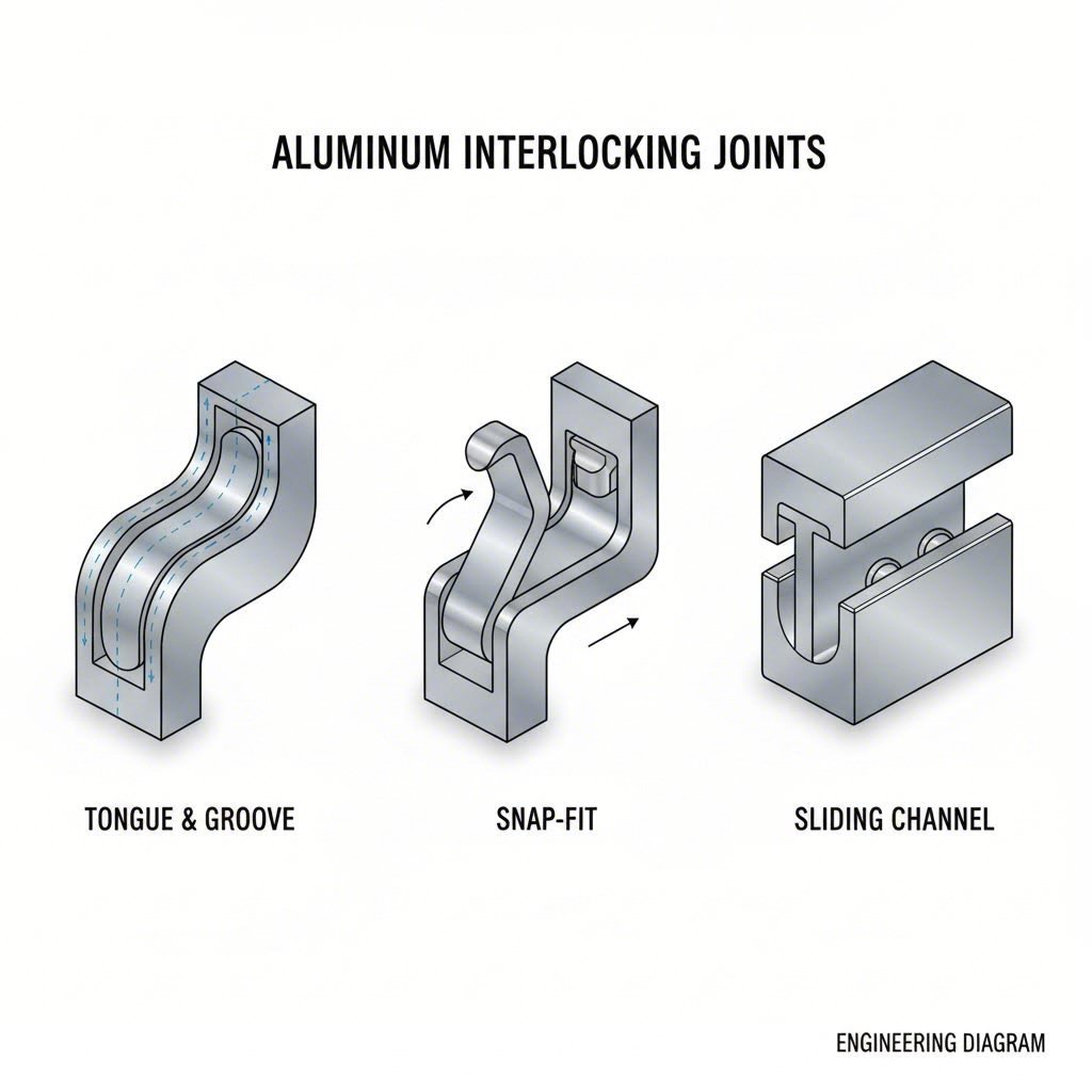
Choosing the right joint type can make or break your project. Sound complex? It doesn't have to be. Once you understand how each interlocking approach works mechanically, selecting the best option for your application becomes straightforward. Let's explore the three primary joint categories engineers rely on most.
Tongue-and-groove joints represent the foundation of interlocking aluminum design. Picture a wooden floorboard connection—one profile features a protruding tongue while its mate has a corresponding groove. When these aluminum tongue and groove profiles come together, they create a flush surface with excellent resistance to vertical displacement.
What makes this joint type special for aluminum u channel and c channel aluminum applications? The answer lies in the geometry. According to the Aluminum Extrusion Council's design manual, interlocking joints are essentially modified tongue-and-groove connections where the mating elements feature curves instead of straight edges. This modification prevents simple straight-line assembly or disassembly.
Here's how it works in practice:
You'll find u channel aluminum profiles with tongue-and-groove features commonly used in flooring systems, wall panel assemblies, and modular enclosures where seamless surfaces matter.
When you need a joint that locks into position without supplemental fastening, snap-fit designs deliver. These self-locking connections rely on aluminum's natural ductility—its ability to flex without permanent deformation.
Imagine pressing two profiles together. The mating parts exert a cam action on each other, flexing until one element slips past a raised lip on the other. Once past this lip, the flexed sections snap back to their original shape, and the lip prevents separation. The result? A joint that cannot be disassembled unintentionally.
Sliding channel connections—sometimes called slip-fit joints—work differently. You assemble these by sliding two mating parts together along their length, similar to how an aluminum i channel might capture a panel edge. While this approach creates reliable strength, it can be challenging in tight spaces where you can't access the full profile length.
Consider these key differences when specifying your joint type:
Which joint type fits your application? This comparison breaks down the critical factors engineers must consider:
| Criteria | Tongue-and-Groove | Snap-Fit | Sliding Channel |
|---|---|---|---|
| Assembly Method | Rotational motion (typically 45°) | Direct push with cam action flex | Lengthwise sliding motion |
| Load Capacity | High resistance to vertical and horizontal loads when secured | Excellent shear resistance; moderate tensile strength | Strong along profile length; may require end restraints |
| Disassembly Ease | Moderate—requires counter-rotation and access to profile ends | Difficult—designed to prevent unintentional release | Easy—slide apart when end access available |
| Best Applications | Flooring systems, architectural panels, trailer decking | Permanent enclosures, security covers, tamper-resistant assemblies | Adjustable frames, removable access panels, modular systems |
| Supplemental Fastening | Often required at ends or cross-members | Typically self-sufficient | May need end caps or retention clips |
The right choice depends on your specific requirements. Need easy field maintenance? Sliding channels give you flexibility. Concerned about unauthorized disassembly? Snap-fit designs provide inherent security. Building a trailer floor or architectural system where profiles must stay locked under vibration and load? Tongue-and-groove with proper end restraints offers proven performance.
Understanding these mechanical principles helps you specify joints that won't fail in service. But geometry alone doesn't guarantee success—dimensional tolerances play an equally critical role in determining whether your interlocking extrusions perform as designed.
You've selected the perfect joint type for your application. Now comes the question that separates successful projects from costly failures: how precise do your dimensions need to be? When specifying interlocking aluminum extrusions, dimensional tolerances aren't just technical details—they determine whether your joints lock securely or fail under load.
Here's the reality most manufacturers won't tell you: even beautifully designed interlocking profiles can fail if tolerance specifications don't account for real-world conditions. Let's explore what engineers must consider when specifying aluminum channel sizes and clearance requirements.
Dimensional tolerance defines the acceptable variation in size and shape of your extruded profiles. For interlocking applications, these variations directly impact joint performance. Too loose, and your connection rattles or separates. Too tight, and assembly becomes impossible—or worse, profiles crack during installation.
According to Mifa's precision extrusion specifications, advanced manufacturers can achieve dimensional tolerances starting from ±0.02 mm for critical applications. However, standard aluminum extrusion tolerances typically range wider, which means engineers must carefully evaluate whether their interlocking design requires precision-grade production.
When reviewing aluminum channel dimensions for interlocking profiles, you'll encounter six primary tolerance categories that affect joint performance:
For interlocking joints specifically, shape deviation and dimensional accuracy demand the closest attention. An aluminum c channel dimensions chart might show standard tolerances acceptable for general structural use, but interlocking features often require tighter specifications. When mating profiles must rotate into position, even small deviations compound across the joint interface.
Clearance—the intentional gap between mating surfaces—might seem counterintuitive when you want a tight connection. But here's what experienced designers know: some clearance is essential for successful assembly and long-term performance.
Think about what happens during assembly. You're rotating one profile into another, and the curved interlocking features must slide past each other before snapping into position. Without adequate clearance, friction prevents engagement. With too much clearance, the joint becomes sloppy and loses load-bearing capacity.
The specification process for aluminum c channel sizes and other interlocking profiles must balance these competing requirements:
When specifying extruded aluminum sizes for custom interlocking profiles, work backward from your most demanding condition. If the joint must assemble in cold weather and operate in hot environments, your clearance specification must accommodate the full temperature range your application will experience.
Here's a topic you won't find in most competitor content: thermal expansion can make or break interlocking aluminum connections. Aluminum expands and contracts significantly with temperature changes—and when interlocking features are designed without this consideration, failures follow.
According to research on designing mechanical joints for extreme temperatures, thermal expansion introduces several challenges. High temperatures can lead to deformation and accelerate wear at joint interfaces, while extreme cold makes materials more brittle and prone to cracking under assembly stress.
What does this mean practically for interlocking extrusions? Consider these scenarios:
Engineers can employ several strategies to address thermal effects in interlocking joint design. Selecting materials with similar thermal expansion rates reduces stress at the joint interface. Incorporating flexible design elements—like slightly looser tolerances or expansion gaps—allows movement without compromising connection integrity. For aluminium trim channel applications in architectural settings, protective coatings can also help manage thermal stress by reducing surface temperature extremes.
The relationship between die design and final joint performance is direct and unforgiving. Your interlocking profile can only be as precise as the die that creates it.
During extrusion, heated aluminum flows through the die opening under tremendous pressure. The die's geometry determines the profile's cross-section, but several factors influence final dimensional accuracy:
For interlocking applications, die design must anticipate these factors. Working with experienced extrusion partners who understand interlocking geometry is essential. They can adjust die dimensions to compensate for known process variations, ensuring the finished profiles meet your tolerance specifications.
Ready to specify your own interlocking extrusion? The process requires clear communication of your tolerance requirements. Use this checklist when developing specifications:
Reference an aluminum channel sizes chart from your potential supplier to understand their standard capabilities. If your interlocking design requires tighter tolerances than standard production, discuss precision extrusion options early in the specification process.
Getting tolerances right prevents the joint failures that plague poorly specified projects. But tolerances alone don't guarantee success—the aluminum alloy you select also plays a critical role in how your interlocking profiles perform over time.
You've nailed your joint design and tolerance specifications. But here's a question that trips up even experienced engineers: which aluminum alloy should you choose? The answer directly impacts whether your interlocking profiles perform flawlessly for decades—or fail prematurely under stress.
When specifying extruded aluminum channel products, alloy selection often gets treated as an afterthought. That's a mistake. The alloy you choose affects everything from how precisely the die can form your interlocking features to how well those joints resist corrosion over time. Let's break down what you need to know.
Two alloys dominate the interlocking extrusion landscape: 6063 and 6061. Both belong to the 6000 series, meaning they're primarily alloyed with magnesium and silicon. But the differences between them—though subtle—matter significantly for interlocking applications.
According to Gabrian International, alloy 6063 is often called "architectural aluminum" because it's been optimized for extrudability. It provides a high-quality surface finish that anodizes beautifully. For 6063 classification, the magnesium content must fall between 0.45 and 0.9%, with silicon between 0.2 and 0.6%.
Alloy 6061, on the other hand, earns the nickname "structural aluminum." It contains higher concentrations of both alloying elements—magnesium between 0.8 and 1.2%, silicon between 0.4 and 0.8%. This composition delivers a better strength-to-weight ratio but slightly reduced corrosion resistance compared to 6063.
What does this mean for your interlocking design? Consider these alloy selection criteria:
Here's something most suppliers won't explain: your alloy choice directly influences how well your interlocking joints engage and hold together over time.
Formability plays a critical role in snap-fit interlocking designs. Remember how these joints rely on the aluminum flexing during assembly before snapping back into position? The alloy must possess sufficient ductility to flex without cracking—yet enough spring-back to lock securely. Research on aluminum formability demonstrates that properties like strain hardening exponent and anisotropy directly affect how sheet and extruded aluminum behaves under deformation.
For interlocking aluminum channels specifically, consider how alloy properties translate to joint performance:
For trailer and transportation applications—where aluminum channels experience constant vibration and varying loads—6061 in T6 temper often proves the better choice. Its higher strength handles dynamic stresses more effectively. For architectural applications using alum c channel or aluminium c channel profiles where appearance and corrosion resistance matter most, 6063 delivers superior results.
Different industries demand different performance characteristics from their interlocking extrusions. Here's how alloy selection aligns with common applications:
Architectural Applications: Building facades, window systems, and decorative trim typically use 6063 alloy. The excellent surface finish enables consistent anodizing across large installations, while adequate strength handles wind loads and thermal cycling. When specifying 6061 aluminum u channel profiles for structural architectural elements, you gain additional load capacity—but may sacrifice some aesthetic consistency in anodized finishes.
Industrial Framework: Equipment enclosures, machine guards, and conveyor systems often benefit from 6061's superior machinability and strength. When your interlocking profiles require precision drilling or threading for supplemental fasteners, 6061 cuts more cleanly and produces better threads.
Transportation and Trailer: Flooring systems and structural deck components face demanding conditions—heavy loads, vibration, weather exposure, and chemical contact. Many manufacturers select 6061-T6 for its high strength, though 6063 may suffice for lighter-duty applications where corrosion resistance takes priority.
Your alloy selection also determines which surface treatments work best—and how those treatments affect interlocking joint performance.
Anodizing creates a hard oxide layer that improves wear resistance at joint interfaces. This matters because interlocking features contact each other under load, and surface wear can gradually loosen connections. According to manufacturing guidelines from ALLWIN Hardware, anodizing increases corrosion resistance while strengthening the surface against abrasion—making it ideal for interlocking profiles in demanding environments.
However, anodizing adds thickness to your profile surfaces. For tight-tolerance interlocking joints, you must account for this dimensional change during die design. A coating that adds 0.0005 to 0.001 inches per surface might seem trivial—but when both mating profiles are anodized, the cumulative effect can significantly affect joint clearance.
Powder coating provides excellent protection for outdoor applications, but consider how coating thickness affects interlocking engagement. Unlike anodizing, which converts surface aluminum to oxide, powder coating adds a distinct layer on top of the base metal. Specify masking for critical interlocking features if coating buildup would prevent proper joint engagement.
PVDF (polyvinylidene fluoride) coatings offer superior UV resistance and weatherability for architectural applications. They're thinner than powder coatings, causing less interference with interlocking geometry—but they require careful surface preparation to ensure adhesion doesn't fail at joint interfaces where movement occurs.
Understanding how alloy properties and surface treatments interact with your interlocking design prevents the kind of failures that only reveal themselves after installation. With the right alloy selected, you're ready to explore where these self-connecting profiles deliver their greatest advantages—from trailer decks to architectural frameworks.
Where do interlocking aluminum extrusions truly shine? The answer spans industries you might expect—and some that might surprise you. From the trailer beneath an 18-wheeler to the sleek facade of a modern office building, these self-connecting profiles solve problems that traditional fastened assemblies simply cannot address.
Let's explore the applications driving demand for interlocking profiles across transportation, construction, and industrial sectors.
When you think about aluminum trailer decking, imagine the punishment these surfaces endure daily. Forklifts rolling across with heavy pallets. Chemical spills from shifting cargo. Temperature swings from freezing winters to scorching summers. Traditional flooring systems—whether wood planks or steel sheets—struggle under these conditions.
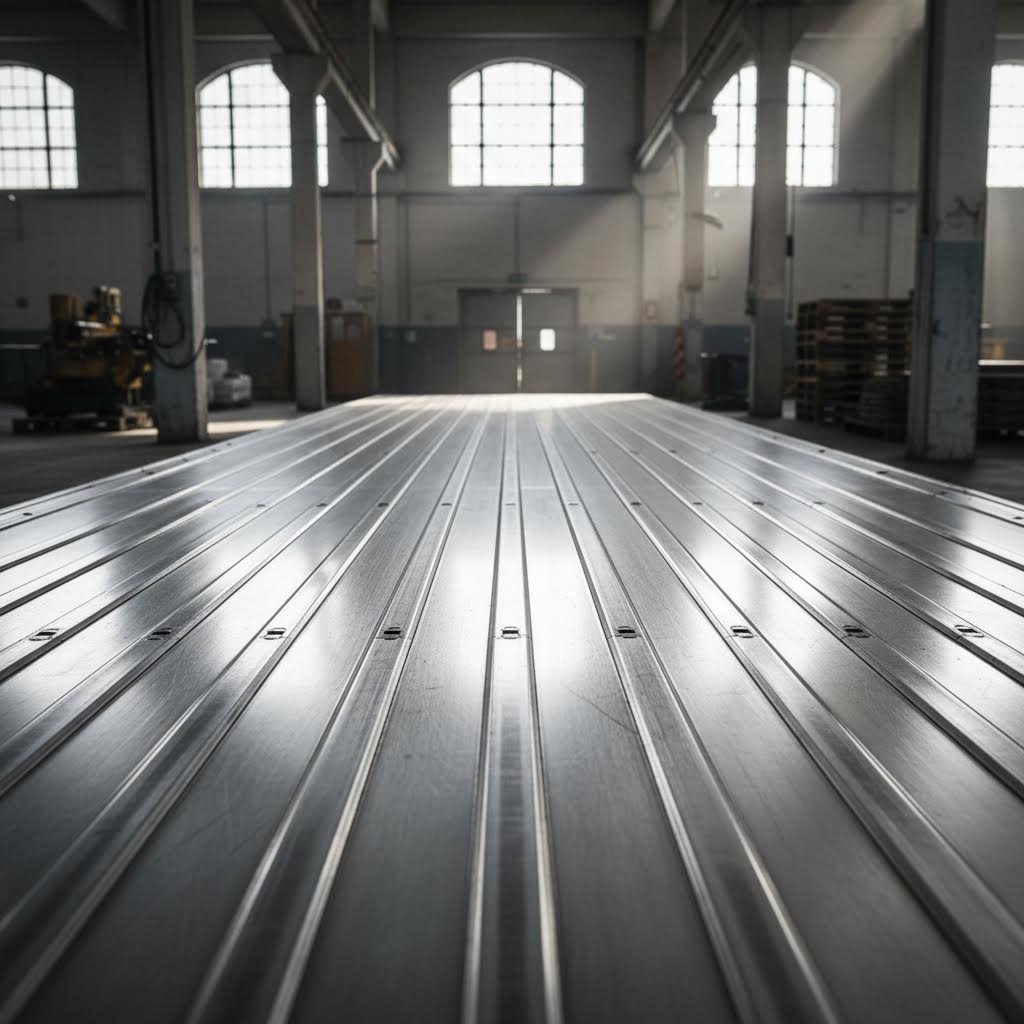
Interlocking aluminum trailer flooring changes the equation entirely. According to Blue Lake Industries, their extruded aluminum interlocking plank floors use an inverted T design where profiles slip together like tongue and groove planks. The result? A seamless surface with no gaps where debris can accumulate or moisture can penetrate.
Here's what makes aluminum trailer decking material superior for transportation applications:
The extruded aluminum trailer flooring available from leading manufacturers typically features standard coverage widths around 6 inches, making installation straightforward across trailer beds of various sizes. Stock lengths of 108 inches accommodate most semi trailer decking applications without requiring custom cutting.
But trailer decking represents just one slice of the transportation sector. Aluminum plank decking systems also serve flatbed trucks, service bodies, and utility trailers. Anywhere you need a durable, lightweight, low-maintenance surface that resists the elements, interlocking aluminum delivers.
What about the aluminum trailer deck on your enclosed trailer or box truck? The same interlocking principles apply. These profiles create floors that won't warp, rot, or corrode—even after years of exposure to whatever cargo throws at them.
Step from the loading dock into the built environment, and you'll find interlocking aluminum extrusions solving entirely different challenges. In architectural applications, these profiles enable designs that would be impractical—or impossible—with traditional fastened systems.
According to industry market analysis, rising demand for energy-efficient building systems drives significant growth in this sector. Interlocking profiles enable superior thermal breaks in windows and doors, where the self-connecting geometry eliminates the thermal bridging that occurs with screw-fastened assemblies.
Consider these architectural applications where interlocking designs excel:
The industrial sector presents its own unique demands. Here, interlocking extrusions form the backbone of equipment enclosures, machine guards, conveyor frames, and automation systems. The ability to assemble and reconfigure without drilling or welding saves hours of production downtime.
Industrial framework applications typically include:
You might wonder: why not just use screws, bolts, or rivets? Traditional fasteners certainly work—but interlocking profiles offer advantages that matter in specific scenarios.
First, consider vibration. In transportation and industrial applications, fasteners work loose over time. Every bump in the road, every machine cycle creates micro-movements that gradually loosen threaded connections. Interlocking joints resist this because their geometry prevents straight-line separation—vibration can't shake apart what physics won't allow to come apart.
Second, think about thermal cycling. Aluminum expands and contracts significantly with temperature changes. Rigid fastener connections create stress concentrations that can lead to fatigue cracking around bolt holes. Interlocking joints allow controlled movement along the profile length, distributing thermal stress across the entire joint interface.
Third, examine installation speed. Snapping or sliding profiles together takes seconds. Drilling, tapping, and fastening takes minutes per connection—and those minutes multiply across large assemblies. For high-volume production or field installation where labor costs matter, interlocking designs slash assembly time.
Finally, consider aesthetics. Exposed fastener heads interrupt clean surface lines. Interlocking joints hide the connection mechanism within the profile geometry, creating seamless appearances that architects and designers prefer.
The interlocking extrusion market serves two distinct needs: standard off-the-shelf products and custom-designed profiles.
Standard interlocking profiles—like the trailer decking extrusions mentioned earlier—offer immediate availability and proven performance. These products suit applications where established dimensions and joint configurations meet your requirements. You'll find standard interlocking profiles serving:
Custom interlocking solutions become necessary when your application demands unique geometries, specific load requirements, or integration with proprietary systems. The custom route requires die development and higher minimum order quantities—but delivers profiles precisely matched to your needs.
Market trends indicate growing demand for customization, particularly in cleanroom construction, specialized transportation equipment, and modular building systems. Manufacturers offering end-to-end capabilities—from die design through surface treatment and fabrication—simplify the custom development process for engineers specifying new interlocking profiles.
Whether you select standard products or pursue custom development, successful implementation depends on proper installation techniques. The next section reveals the assembly methods that ensure your interlocking joints perform as designed.
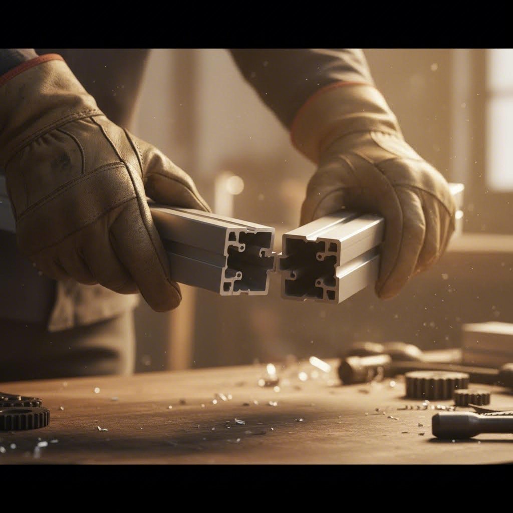
You've selected the right joint type, specified proper tolerances, and sourced quality profiles. Now comes the moment of truth: installation. Surprisingly, most manufacturers provide little guidance on actually assembling interlocking aluminum extrusions—leaving installers to figure things out through trial and error. Let's change that.
Proper installation technique determines whether your interlocking joints deliver their designed performance or fail prematurely. The good news? Once you understand the underlying principles, assembly becomes straightforward regardless of which joint type you're working with.
Before you engage your first interlocking connection, preparation sets the stage for success. Rushing this phase leads to the frustrating problems that plague poorly executed installations.
Start by gathering the right tools for your specific application:
Surface preparation often gets overlooked—but contamination at joint interfaces causes more problems than installers realize. According to Inquivix Technologies, extrusion lubricants and release agents are applied during manufacturing to minimize friction between the billet, container, and die. Residues from these compounds can remain on finished profiles, reducing the friction that helps interlocking joints stay engaged.
Clean all mating surfaces before assembly. For standard applications, wiping with isopropyl alcohol removes light contamination. Heavily soiled profiles may require stronger solvents—but always verify compatibility with any surface treatments before applying chemicals to anodized or coated aluminum.
Ready to connect your profiles? The specific technique depends on your joint type, but these sequential steps apply universally:
The rotating motion concept deserves special attention. Unlike simple push-together connections, curved interlocking features require the mating profile to pivot into position. Imagine closing a laptop—the hinge creates an arc of motion rather than straight-line movement. Your interlocking profiles work similarly, with the curved tongue tracing an arc as it rotates into the curved groove.
Each joint category presents unique installation characteristics. Understanding these differences prevents the frustration of forcing connections that require finesse.
Tongue-and-groove installations: These joints typically engage through rotation. Position the mating profile with its tongue resting against the groove opening, then rotate downward while maintaining contact. Consistent pressure along the profile length ensures the joint closes evenly. For aluminum c channel track applications, work from one end toward the other rather than trying to engage the entire length simultaneously.
Snap-fit installations: Apply firm, even pressure until you feel the profile click past the retention feature. Avoid hammering—excessive force can damage the flexing elements that enable snap-fit function. If a snap-fit joint resists engagement, check for debris or burrs rather than applying more pressure.
Sliding channel installations: These connections require access to the profile end. Insert the mating element into the channel track opening, then slide lengthwise until the profiles fully overlap. For long runs, lubrication at the joint interface can ease installation—but use only lubricants compatible with your surface treatment.
Even well-designed interlocking systems present occasional difficulties. Here's how to address the most frequent problems:
Profiles won't engage: Check for burrs at cut ends, manufacturing debris in joint channels, or thermal contraction in cold weather. Light filing removes burrs; compressed air clears debris; warming profiles slightly restores clearance lost to thermal contraction.
Joints engage unevenly: Substrate flatness usually causes this issue. A warped mounting surface transmits its irregularities to your profiles. Shim low spots or use adjustable mounting hardware to establish a level foundation.
Difficulty achieving consistent spacing: Use alignment jigs or temporary spacer blocks between profiles. For metal channel track systems spanning long distances, chalk lines on the substrate help maintain straight runs.
Profiles shift after initial engagement: This indicates the joint geometry allows more movement than your application tolerates. Add supplemental restraints—end caps, cross-member fasteners, or strategic tack welds—to prevent unwanted movement.
Assembly in tight spaces: Sliding connections become challenging when you can't access profile ends. Consider whether alternative joint types might work better, or plan your assembly sequence to engage these connections before surrounding structures limit access.
Proper installation prevents most joint failures—but even correctly assembled interlocking profiles can develop problems over time. Understanding the warning signs and causes of joint failure helps you maintain long-term performance.
What happens when interlocking aluminum extrusions start failing in the field? Most manufacturers stay silent on this topic—leaving engineers and installers to diagnose problems without guidance. Yet understanding failure modes is essential for both preventing issues before they occur and addressing problems when they appear.
The reality? Even properly designed and installed joints can develop issues over time. Environmental factors, material interactions, and operating conditions all influence long-term performance. Let's examine what goes wrong—and how to prevent it.
Joint failures in extruded aluminium channel assemblies typically fall into four categories, each with distinct causes and warning signs.
Thermal Expansion Stress: Remember how aluminum expands and contracts with temperature changes? When interlocking joints can't accommodate this movement, stress concentrates at the connection points. According to research on designing mechanical joints for extreme temperatures, high temperatures can weaken materials and lead to deformation, while extreme cold makes aluminum more brittle and prone to cracking.
Improper Tolerances: Joints specified too tight bind during temperature increases. Joints too loose rattle and wear prematurely. Either extreme accelerates failure—the first through stress cracking, the second through mechanical degradation at contact surfaces.
Corrosion at Joints: When moisture penetrates interlocking interfaces—especially where dissimilar metals contact aluminum—galvanic corrosion attacks the joint. According to corrosion prevention research, saltwater environments can increase corrosion rates by up to 40 times compared to dry conditions.
Mechanical Wear: Vibration, repeated loading, and relative movement between profiles gradually degrade interlocking features. The curved surfaces that enable rotation during assembly slowly wear flat, reducing the mechanical interlock that prevents separation.
Catching problems early prevents catastrophic failures. Watch for these indicators when inspecting aluminium track channel assemblies and other interlocking systems:
Prevention starts at specification—not after installation. When selecting alum channel sizes and joint configurations, factor in your operating environment from the beginning.
Address thermal cycling: For outdoor applications or environments with significant temperature swings, specify adequate thermal clearance. Looser tolerances in joint design reduce fracture risk caused by contraction, while expansion gaps at strategic intervals prevent binding during heat exposure.
Prevent corrosion: When your aluminum trim channel assembly contacts dissimilar metals—particularly stainless steel fasteners—use non-conductive barriers. Plastic washers, neoprene gaskets, or EPDM spacers break the electrical path that enables galvanic corrosion. Seal joints in moisture-prone environments to block water infiltration.
Reduce mechanical wear: Protective coatings on interlocking surfaces extend service life. Anodizing creates a hard oxide layer that resists abrasion at contact points. For metal channel track systems subject to repeated sliding, periodic lubrication with aluminum-compatible products reduces friction wear.
Establish inspection schedules: Regular checks catch developing problems before they cause failures. High-humidity or marine environments demand more frequent inspection—quarterly rather than annually. Document joint condition over time to identify degradation trends.
The connection between proper specification, careful installation, and failure prevention becomes clear when you examine failed joints. Almost every failure traces back to a preventable cause: tolerances that didn't account for thermal movement, missing corrosion barriers, or inadequate surface protection. Getting these details right during design—and working with manufacturers who understand interlocking geometry—eliminates most failure modes before your profiles ever leave the factory.
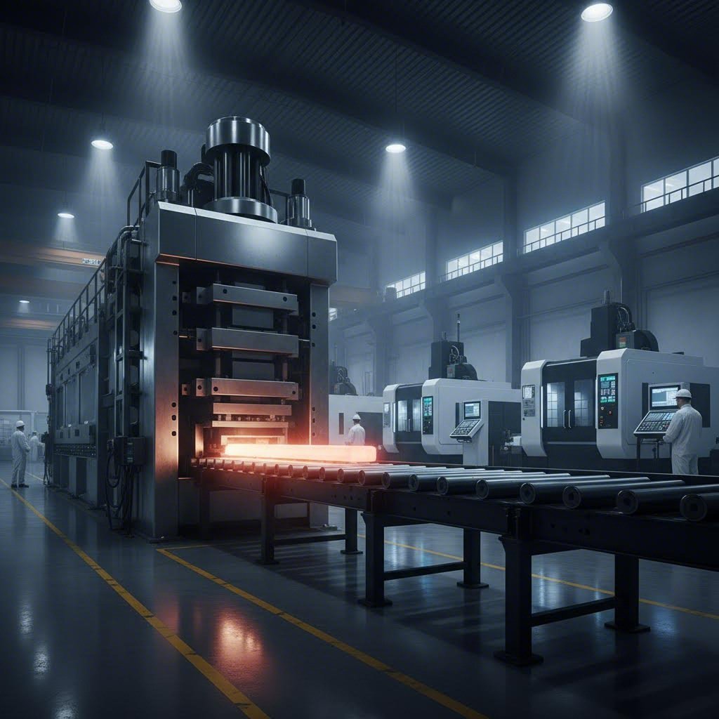
So you've determined that standard interlocking profiles won't meet your project requirements. What happens next? The custom die development process might seem intimidating—but understanding each phase transforms it from a mysterious black box into a manageable engineering project.
Whether you're developing aluminum channel extrusions for a specialized trailer application or creating a proprietary aluminum frame system for architectural use, the path from concept to production follows predictable steps. The key lies in selecting the right manufacturing partner and providing clear specifications from the start.
Custom interlocking profiles begin with die design—and this is where your choice of manufacturing partner matters most. According to Gemini Group's analysis of extrusion dies, the die is the most crucial component in the extrusion process, shaping aluminum under immense pressure with incredible precision and reliability.
What makes die development for interlocking profiles particularly challenging? The curved geometries that enable rotation during assembly demand tighter tolerances than simple structural shapes. Your die designer must account for:
When evaluating potential partners for extruded aluminum u channel or c channel aluminum extrusion projects, look beyond basic extrusion capability. The best partners bring die design expertise in-house rather than subcontracting this critical step. They should demonstrate experience with similar interlocking geometries and provide examples of successful projects.
Shengxin Aluminium exemplifies the comprehensive approach that complex interlocking profiles demand. With over 30 years of industry experience and 35 advanced extrusion presses ranging from 600T to 5500T capacity, they handle everything from delicate architectural profiles to heavy-duty extruded aluminum rails for industrial applications. Their end-to-end support—from die development through mass production—eliminates the coordination headaches that plague multi-vendor projects.
Imagine walking your interlocking design through the production process. Understanding each phase helps you prepare the specifications your manufacturing partner needs—and anticipate the decisions you'll face along the way.
Phase 1: Design Review and Feasibility
You provide initial drawings or CAD files showing your desired profile cross-section. The manufacturer evaluates whether your interlocking geometry is extrudable—and at what cost. Complex u channel aluminum extrusion designs with thin walls or sharp internal corners may require modified geometries to ensure consistent production.
Phase 2: Die Engineering
Die designers translate your profile into tooling specifications. According to industry experts, effective die design requires uniform material flow velocity, optimal bearing lengths, and finite element analysis to model structural integrity and thermal behavior before manufacturing begins. For interlocking profiles, this phase must verify that mating parts will actually fit together within production tolerances.
Phase 3: Die Fabrication
Skilled toolmakers machine the die from H13 tool steel—chosen for its excellent thermal conductivity, wear resistance, and toughness. The die typically includes multiple components: for hollow or semi-hollow interlocking profiles, this means a mandrel, die cap, and backer working together as a unit.
Phase 4: Trial Extrusions
Initial production runs test whether theory matches reality. Engineers measure trial profiles against specifications, checking that interlocking features engage properly. Adjustments to die bearing lengths or geometry may be necessary before approval for production.
Phase 5: Production and Deep Processing
With the die proven, full production begins. But extrusion is just the starting point for most interlocking applications. Deep processing transforms raw extrusions into finished components ready for assembly.
This is where capabilities like those offered through Shengxin Aluminium's processing services become essential. State-of-the-art CNC machining centers handle precise cutting to length, drilling for supplemental fasteners, and bending for curved applications. When your aluminum f channel or extruded aluminum rail requires tight-tolerance holes at specific intervals, integrated CNC processing ensures accuracy that hand-drilling can't match.
Ready to initiate your custom interlocking project? Prepare these specifications before approaching potential manufacturing partners:
Your interlocking profiles likely need surface treatment—but choosing the right option requires understanding how each finish affects joint performance.
Anodizing creates a hard aluminum oxide layer that significantly improves wear resistance at interlocking contact points. Shengxin Aluminium offers anodizing in custom colors including champagne and rose gold for architectural applications where aesthetics matter. Remember that anodizing adds dimensional thickness—factor this into your tolerance specifications.
Powder coating provides excellent protection for outdoor installations where UV resistance and color variety matter. The coating layer is thicker than anodizing, so specify masking on critical interlocking features to prevent engagement problems.
PVDF coatings deliver superior weatherability for demanding architectural facades. Their thinner application causes less interference with joint geometry than powder coating while providing exceptional long-term color retention.
Micro-arc oxidation creates exceptionally hard ceramic-like surfaces for the most demanding wear applications. This advanced treatment suits interlocking joints subject to repeated assembly and disassembly cycles.
Not all extrusion manufacturers handle custom interlocking profiles equally well. According to guidance from aluminum processing industry experts, your evaluation should probe die design expertise, press capability, and secondary operation controls.
Ask potential partners these questions:
Manufacturers like Shengxin Aluminium who offer factory-direct pricing combined with comprehensive in-house capabilities—from die development through surface treatment and CNC machining—simplify procurement while ensuring consistent quality across all production phases.
With your custom die developed and production partner selected, one critical step remains: confirming that your specified profiles will perform as intended in your actual application. The final section provides a comprehensive checklist for making that final specification decision.
You've absorbed a tremendous amount of information—from joint mechanics and tolerance specifications to alloy selection and installation techniques. Now comes the decision that matters: translating that knowledge into a specification that delivers reliable performance for your specific application.
Whether you're sourcing channel aluminum for an aluminum trailer floor system or specifying custom alu channel profiles for architectural frameworks, the same fundamental questions apply. Let's synthesize everything into an actionable framework you can use today.
Before contacting aluminum channel suppliers or requesting quotes, work through these critical decisions. Each choice influences the others—so consider them as an integrated system rather than isolated checkboxes.
Start with your application requirements: What loads will your joints handle? What environmental conditions will they face? How critical is disassembly for maintenance? Your answers shape every subsequent specification decision.
According to industry supplier selection guidance, clearly defining your project's technical and logistical needs ensures you choose a supplier who not only has the capacity but also the expertise to deliver exactly what you need. The intended application determines the type of alloy, strength requirements, corrosion resistance, and thermal properties your profiles demand.
Consider this specification checklist before approaching manufacturers:
With specifications in hand, evaluating potential suppliers becomes straightforward. But here's what separates successful projects from frustrating ones: choosing partners who understand the complete lifecycle of aluminum extruded products—not just the extrusion process itself.
According to extrusion selection experts, finding a reliable aluminum extrusion plant involves considering production capacity, quality control systems, technical support capabilities, and after-sales service. The best partners act as extensions of your engineering team rather than simple order-takers.
Look for manufacturers offering these capabilities:
Shengxin Aluminium exemplifies what to look for in a manufacturing partner. With over 30 years of experience serving global markets, their facility houses 35 extrusion presses ranging from 600T to 5500T—meaning they match the right equipment to your profile requirements. Their factory-direct pricing model eliminates middleman markups while their end-to-end capabilities—from die development through surface treatment and CNC processing—deliver complete solutions rather than partial components.
Here's what experienced engineers know: the lowest quoted price rarely delivers the lowest total cost. When evaluating types of aluminum channel suppliers, consider the complete lifecycle from design consultation through long-term performance.
Think about these often-overlooked factors:
Your interlocking extrusion project represents more than a component purchase—it's an investment in system performance. The joint that functions flawlessly for years delivers value that far exceeds the cost difference between adequate and excellent suppliers.
Take the time to specify correctly. Choose partners who understand interlocking geometry. Verify that tolerances, alloys, and surface treatments align with your operating conditions. When you get these fundamentals right, interlocking aluminum extrusions deliver the fastener-free connections, seamless surfaces, and long-term reliability that make them the preferred choice for demanding applications across transportation, architecture, and industrial sectors.
Interlocking aluminum extrusions are custom-designed profiles featuring complementary geometries—such as curved tongue-and-groove, snap-fit, or sliding channel connections—that connect without traditional fasteners. They work through rotational motion assembly, where curved elements require pivoting to engage and counter-rotating to release, creating joints that resist straight-line separation under load. This design eliminates visible hardware while providing superior joint integrity for applications ranging from trailer flooring to architectural frameworks.
Three primary interlocking joint types serve different applications: tongue-and-groove joints use modified curved connections requiring rotational engagement, ideal for flooring and panel systems; snap-fit designs rely on aluminum's ductility to flex and lock permanently, perfect for tamper-resistant enclosures; and sliding channel connections assemble lengthwise for adjustable systems requiring field modification. Each type offers distinct advantages in load capacity, disassembly ease, and application suitability.
Select 6063 alloy when your interlocking design features intricate geometries, thin walls, or requires superior anodized finishes—it flows more easily through complex dies and offers better corrosion resistance. Choose 6061 alloy for structural applications demanding higher strength, better machinability for secondary operations, or heavy-load trailer and industrial uses. Both alloys work well in interlocking applications, but 6061-T6 handles dynamic stresses better while 6063 delivers exceptional aesthetic consistency.
Common failure causes include thermal expansion stress from inadequate clearance allowances, improper tolerance specifications causing binding or looseness, galvanic corrosion at dissimilar metal contacts, and mechanical wear from vibration. Prevent failures by specifying thermal clearances for your temperature range, using non-conductive barriers between dissimilar metals, applying protective anodizing to wear surfaces, and establishing regular inspection schedules—especially in marine or high-humidity environments.
Prioritize manufacturers with in-house die development expertise, appropriate press capacity ranging from smaller tonnage for intricate profiles to larger presses for structural sections, integrated CNC machining and surface treatment capabilities, and documented quality systems. Partners like Shengxin Aluminium offer factory-direct pricing with end-to-end support from die development through mass production, eliminating coordination issues between multiple vendors while ensuring consistent quality across all production phases.



 خدمة الإنترنت
 0086 136 3563 2360
 sales@sxalu.com
 +86 136 3563 2360
 العربية
 English
 français
 Deutsch
 русский
 español
 português
 ไทย
ไทย Việt
Việt Українська