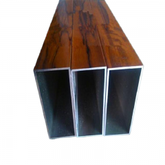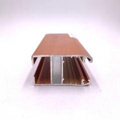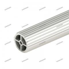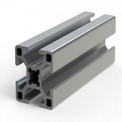
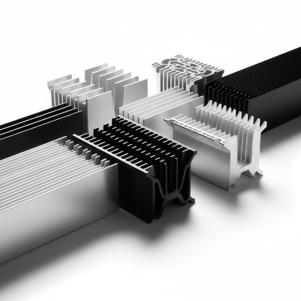
Ever wondered how your laptop stays cool during hours of use, or how LED lights maintain their brightness without overheating? The answer often lies in a deceptively simple component: the heat sink. More specifically, aluminum extrusion heat sink profiles have become the backbone of thermal management across countless industries.
Imagine squeezing toothpaste through a tube—except instead of paste, you're forcing heated aluminum alloy through a specially designed mold called a die. The result? A continuous metal profile with fins and grooves specifically engineered to pull heat away from electronic components and release it into the surrounding air. This process, known as heat sink extrusion, produces remarkably consistent cooling solutions at a fraction of the cost of other manufacturing methods.
An extruded heat sink is a thermal management component created by forcing aluminum alloy through a shaped die, producing a profile with increased surface area designed to transfer heat from electronic components into the ambient environment through convective cooling.
You might be asking: why choose an extruded heatsink over other cooling options? The answer comes down to three key advantages.
First, the extrusion process allows for complex cross-sectional designs that would be difficult or expensive to achieve otherwise. Unlike die casting, which forces molten metal into a mold and often produces seams and imperfections, extrusion creates clean, continuous fin patterns with fine surface finishes. This translates to better thermal performance right out of the manufacturing line.
Second, aluminum heat sinks produced through extrusion offer exceptional design flexibility. Manufacturers can create thin, closely spaced fins that maximize the contact area with air—all without adding unnecessary weight or bulk. When you browse an aluminum extrusion catalog, you'll notice profiles ranging from simple rectangular fins to intricate multi-channel designs, each optimized for specific cooling scenarios.
Third, cost efficiency makes extrusion the go-to choice for most applications. The die engineering costs are significantly lower compared to casting methods, and the streamlined production process keeps per-unit expenses manageable even for custom designs.
So why aluminum specifically? This lightweight metal strikes an ideal balance between thermal conductivity, weight, and affordability. Common alloys like AL6061 and AL6063 conduct heat efficiently while remaining easy to shape during the extrusion process.
Here's the physics behind it: when your device operates, the heat sink's base makes direct contact with the heat-generating component—typically a CPU, LED chip, or power transistor. The fins absorb this thermal energy and disperse it into the surrounding environment. More fins mean more surface area, and more surface area means faster heat dissipation.
Most extruded heatsinks function as passive devices with no moving parts, relying purely on natural convection. However, they can also work alongside cooling fans or liquid cooling systems for high-performance applications. The beauty of this approach? Reliability. With no mechanical components to fail, a well-designed aluminum heat sink can outlast the device it protects.
Additionally, aluminum naturally resists corrosion, and surface treatments like anodizing or powder coating extend this protection even further. Whether you're designing for consumer electronics, industrial machinery, or outdoor LED lighting, these profiles deliver dependable thermal management year after year.
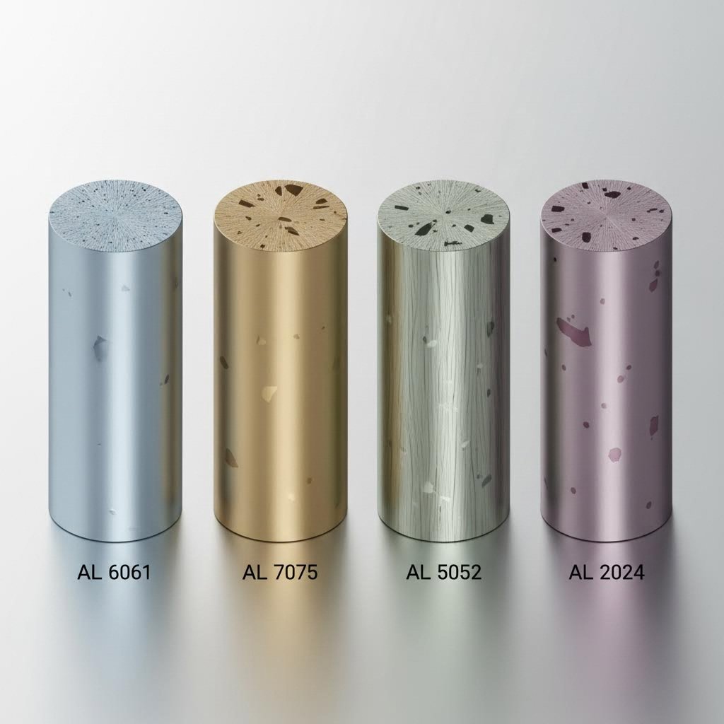
Now that you understand how extruded heat sinks work, you're probably wondering: which aluminum alloy should I actually use? This question trips up many engineers because the answer isn't as straightforward as picking the material with the highest thermal conductivity. Let's break down the real trade-offs so you can make an informed decision for your project.
Here's something that surprises many designers: the alloy with the best thermal performance isn't always the best choice for aluminum heatsinks. Pure aluminum (like 1050) offers excellent heat transfer properties, but it's mechanically too soft to hold up in most applications. That's why the 6000 series alloys dominate the heat sink market—they deliver the right combination of thermal performance, structural integrity, and manufacturability.
When comparing aluminum extrusion profiles for thermal applications, thermal conductivity becomes your primary performance metric. This value, measured in watts per meter-kelvin (W/m·K), tells you how efficiently heat moves through the material. Higher numbers mean faster heat transfer from your component to the cooling fins.
Consider this comparison based on industry data:
| Alloy | Thermal Conductivity (W/m·K) | Extrudability | Typical Applications | Relative Cost |
|---|---|---|---|---|
| 1050 | 229 | Good | Rarely used—too soft for heat sinks | Low |
| 6063 | 201 | Excellent | LED lighting, consumer electronics, general-purpose cooling | Low to Medium |
| 6061 | 152-166 | Good | Power electronics, industrial equipment, structural heat sinks | Medium |
| 6060 | 166 | Excellent | Thin-walled profiles, architectural applications | Low to Medium |
Notice something interesting? The 6063 alloy actually outperforms 6061 in thermal conductivity by a significant margin—roughly 20-30% better heat transfer. Yet both alloys remain popular choices for extruded aluminum heatsink applications. Why? Because thermal conductivity is only part of the equation.
Imagine you're designing a heat sink for two different scenarios. The first is an LED downlight where weight matters and thermal loads are moderate. The second is a power inverter that generates substantial heat and requires a robust mounting structure. Would you choose the same alloy for both? Probably not.
Choose 6063 when:
Choose 6061 when:
Here's the practical reality: the thermal conductivity difference between 6000 series alloys is relatively minimal in real-world applications. According to thermal management experts, maximizing the surface area of your aluminium heatsinks and optimizing airflow often matters more than squeezing out a few extra W/m·K from your alloy choice.
What about those high-conductivity pure aluminum alloys like 1050 or 1100? While their 229 W/m·K rating looks attractive on paper, these materials lack the mechanical properties needed for most heat sink applications. They dent easily, can't hold tight tolerances, and tend to deform under mounting pressure. The 6000 series strikes the ideal balance—strong enough to maintain dimensional stability while still moving heat efficiently.
One final consideration: temper matters too. The same alloy can exhibit different properties depending on its heat treatment. For instance, 6061-T6 (solution-treated and artificially aged) offers optimized strength, while the O temper (annealed) provides slightly better thermal conductivity at the expense of mechanical performance. Always specify both alloy and temper when ordering aluminum heatsinks to ensure you get exactly the properties your design requires.
You've selected your alloy—now what happens next? Understanding the extrusion manufacturing process helps you design heatsink extrusion profiles that are not only thermally efficient but actually manufacturable. Too many engineers create beautiful CAD models only to discover their intricate fin patterns can't survive the die. Let's walk through the journey from raw aluminum billet to finished heat sink, focusing on the constraints that should shape your design decisions.
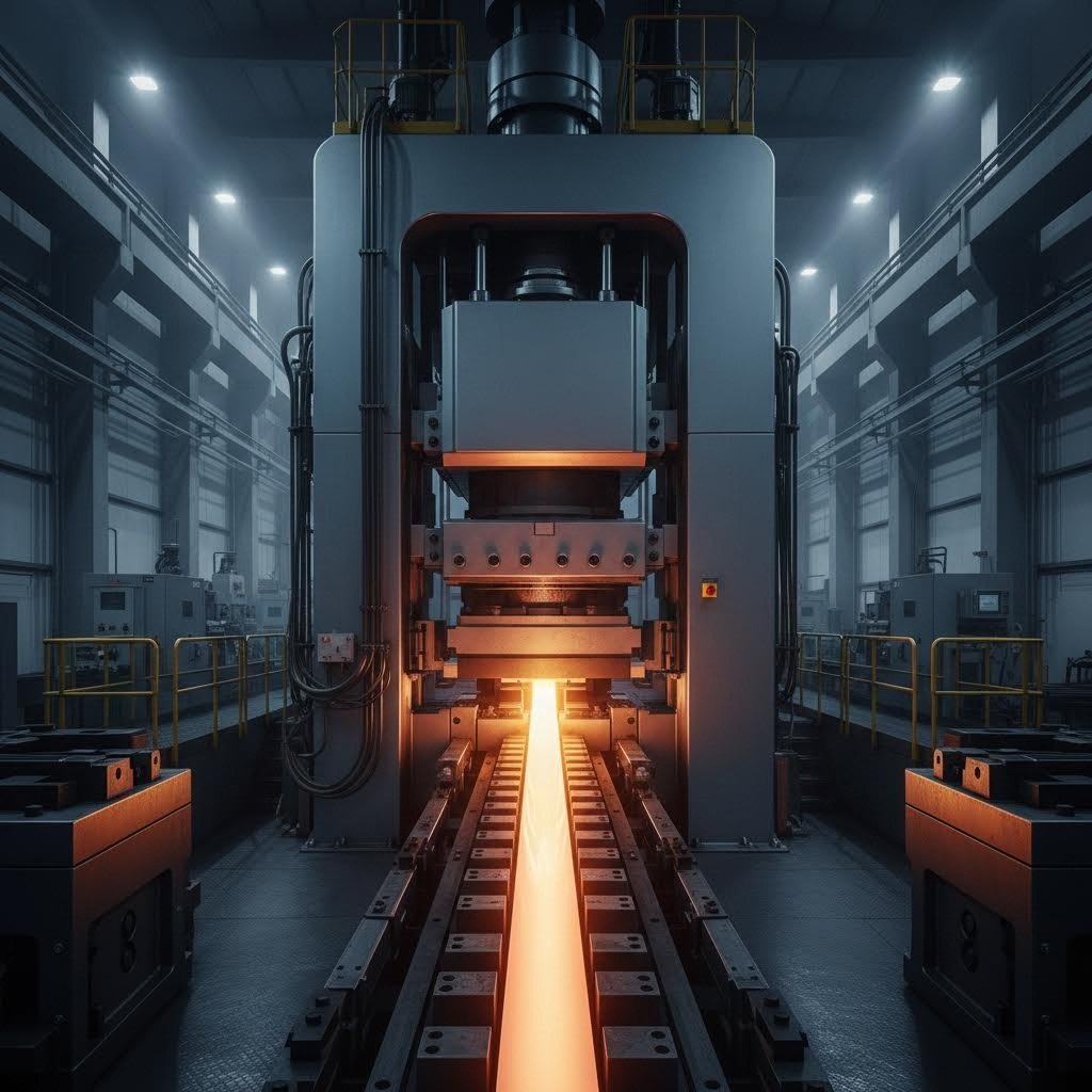
Picture a hydraulic press generating thousands of tons of force, pushing a glowing aluminum cylinder through a steel opening no bigger than your hand. That's hot extrusion in a nutshell. But the details matter enormously for thermal designers.
The process begins with billet preparation. According to manufacturing specialists, cylindrical aluminum billets are heated to approximately 400–500°C, reaching a plastic state where the metal flows like thick putty. This temperature window is critical—too cold and the aluminum resists flow, potentially cracking the die; too hot and you risk surface defects or dimensional instability.
Next comes the actual extrusion. A powerful hydraulic ram forces the heated billet through a hardened steel die that contains the negative image of your heat sink profile. As the aluminum flows through the die opening, it takes on the cross-sectional shape—base, fins, and all—emerging as a continuous length of extruded aluminum profiles.
Here's what many designers overlook: the die itself represents a significant investment. Industry documentation indicates that die costs typically range from $1,000 to $20,000 depending on profile complexity. These dies are press-specific and proprietary—they won't transfer between manufacturers. This reality makes design-for-manufacturability essential from the start.
After extrusion, the profile undergoes quenching—rapid cooling that locks in desired material properties. For 6063 aluminum heatsinks, proper quenching ensures the alloy can later achieve optimal strength through aging treatment. The cooled profile is then cut to length, and secondary operations like CNC machining add mounting holes, tapped threads, or custom features.
Now for the question every thermal engineer eventually asks: how tall and thin can I make my fins? The answer involves a concept called aspect ratio—the relationship between fin height and the gap between fins.
Think of it this way: as aluminum flows through the die, it must fill every corner of that intricate fin pattern. Tall, closely-spaced fins create narrow channels that resist metal flow. Push the geometry too far, and you'll see incomplete fills, warped fins, or die failures.
According to extrusion design guidelines, manufacturers can typically achieve aspect ratios up to 6:1 for profiles fitting within a 21-inch circle size. Smaller profiles allow more aggressive geometries—up to 16:1 for circle sizes under 12 inches. However, these maximums assume ideal conditions; your specific alloy, press tonnage, and die design all influence what's achievable.
When designing your aluminum extrusion profile, consider these manufacturing constraints:
Here's a practical insight that saves headaches: the relationship between press tonnage and profile aluminum extrusion complexity isn't just about raw power. Larger presses operating at lower relative pressure can extrude at reduced temperatures, improving material properties and surface finish. If your thermal design pushes manufacturability limits, working with a manufacturer that operates higher-tonnage presses provides additional design freedom.
Tolerances also deserve attention. Standard aluminium heatsink extrusion follows Aluminum Association specifications, with flatness tolerances ranging from 0.004 to 0.012 inches per inch of width. For heat sinks requiring precise mating surfaces—like those contacting semiconductor packages—plan for secondary machining operations. CNC surfacing can achieve flatness within 0.001 inch T.I.R. and surface roughness of 20 micro-inches, ensuring optimal thermal interface contact.
One final consideration before moving to fin optimization: minimum order quantities. Extrusion mills typically require 500 to 4,000 pounds per order depending on profile size. For prototype quantities, this often means purchasing extra material or finding distributors who stock standard profiles. Understanding these manufacturing realities upfront prevents costly surprises when transitioning from design to production.
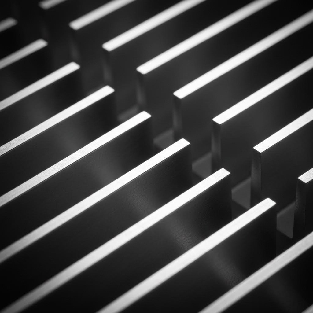
You've chosen your alloy and understood the extrusion process—now comes the design decision that makes or breaks thermal performance: fin geometry. Here's a counterintuitive truth that catches many engineers off guard: adding more fins doesn't always mean better cooling. In fact, cramming too many aluminum heat sink fins into your profile can actually reduce heat dissipation. Let's explore why this happens and how to optimize your heatsink profile for real-world conditions.
The physics behind this paradox involves something called boundary layer interference. When air flows past a heated fin surface, it forms a thin layer of warmed air that clings to the metal. In tightly packed fins, these thermal boundary layers from adjacent surfaces merge together, choking off fresh cool air and dramatically reducing convective heat transfer. Understanding this phenomenon is essential for designing extruded heat sink profiles that actually perform as intended.
Imagine two identical finned aluminum heat sink designs—same alloy, same total surface area, same fin height. One cools a passively cooled LED driver; the other sits in a server with powerful fans. Would you use the same fin spacing for both? Absolutely not. The cooling method fundamentally changes the optimal geometry.
Natural convection relies entirely on buoyancy-driven airflow. Warm air rises from heated fin surfaces, drawing cooler ambient air in from below. This gentle air movement demands generous spacing between fins. According to thermal design guidelines, natural convection applications require a minimum fin spacing of 4mm to allow smooth airflow. Finer spacing restricts the buoyant flow, negating any benefit from increased surface area.
Research published in Applied Sciences provides more precise guidance through the concept of thermally optimum fin spacing. Using the Bar-Cohen and Rohsenow correlation, engineers can calculate the ideal gap for maximum heat dissipation under natural convection. For a typical vertical heat sink with 100mm fin length operating at moderate temperature differences, this optimum falls around 7.5-8mm—significantly wider than many designers initially assume.
Here's what the research reveals about fin spacing-to-thickness ratio (S*) in natural convection:
Forced convection changes the equation dramatically. When fans push air through fin channels, you can pack fins much more tightly because the mechanical airflow overcomes boundary layer buildup. Spacing as narrow as 1.5-2mm becomes practical, allowing significantly more surface area within the same envelope. The trade-off shifts from boundary layer interference to pressure drop—tighter fins require more powerful fans to maintain adequate airflow.
Design guidelines for different cooling scenarios:
Now consider fin height. Taller fins provide more surface area—sounds like a clear win, right? Not quite. As fins grow taller, two problems emerge that limit practical height.
First, fin efficiency drops with increasing height. Heat must conduct from the base all the way to the fin tip before it can transfer to the air. The longer this conduction path, the cooler the fin tip becomes relative to the base. A fin tip that's barely warmer than ambient air contributes almost nothing to cooling. Research data shows fin efficiency declining steadily as the height-to-spacing ratio (H*) increases—what starts as 90%+ efficiency at H* = 1.1 can drop below 70% at H* = 7.8.
Second, diminishing returns set in as you add height. The same numerical analysis demonstrates that while heat dissipation rate increases nearly linearly with fin height, the mass-specific heat dissipation rate (heat removed per gram of aluminum) plateaus quickly. After a certain point, you're adding weight and cost without proportional thermal benefit.
So what height-to-gap ratios actually work? Consider these guidelines for extruded aluminum heat sink material:
There's also the matter of thermal spreading resistance in the base. Heat entering the base from a concentrated source (like a small chip) must spread laterally before conducting up into the fins. If fins are spaced too far apart or the base is too thin, heat can't reach outer fins effectively, leaving them underutilized. A thicker base improves spreading but adds weight; optimizing this trade-off often requires thermal simulation for complex layouts.
One practical takeaway: fin angle matters too. Most extruded heat sink profiles incorporate a slight draft angle of approximately 3 degrees on fin sidewalls. This isn't just a manufacturing necessity—it actually improves airflow by preventing air from getting trapped in parallel channels. The angled surfaces guide convective currents more efficiently than perfectly vertical walls.
When you're specifying your next heatsink profile, remember that optimal fin design depends entirely on your cooling method and thermal constraints. Natural convection rewards wider spacing and moderate heights; forced convection allows tighter packing for maximum surface area. Getting this balance right often matters more than selecting the highest-conductivity alloy or the most sophisticated surface treatment.
You've optimized your fin geometry and selected the right alloy—but here's a detail that often gets overlooked: the surface finish on your extruded aluminum heat sink can change thermal performance by a factor of 17. Sounds dramatic? Consider this: unfinished aluminum has an emissivity of roughly 0.05, meaning it radiates only 5% as effectively as a perfect black body. Anodize that same surface, and emissivity jumps to approximately 0.85. That's the difference between a heat sink that barely radiates and one that actively sheds thermal energy into its surroundings.
But here's where it gets interesting: higher emissivity doesn't always translate to better cooling. The right finish depends entirely on your cooling method, operating environment, and even aesthetic requirements. Let's break down when each option makes sense for your heatsink profiles.
Unlike paint or powder coating, anodizing doesn't add a layer on top of aluminum—it transforms the surface itself. The electrochemical process thickens the natural oxide layer, creating a porous, microscopically textured surface that dramatically improves radiation heat transfer.
When does this matter? Radiation becomes significant when convective airflow is limited. Think of a sealed enclosure, a passively cooled LED fixture, or electronics operating in still air. In these scenarios, a substantial portion of heat leaves through thermal radiation, and that 0.85 emissivity makes a measurable difference.
However, for actively cooled systems with strong forced airflow, the story changes. According to thermal analysis, the improved radiation from anodizing has less overall impact on active heatsink aluminium designs because convection dominates the heat transfer equation. The fan moves so much air past the fins that radiation contributes a smaller percentage of total cooling.
Here's a practical guideline:
What about color? Many designers assume black anodized aluminum extrusion shapes perform better thermally than colored alternatives. Surprisingly, this is largely a myth. Whether your heat sink is black, blue, or gold anodized, the thermal radiation performance remains essentially identical. The emissivity improvement comes from the oxide layer's texture and thickness, not the dye color. Choose your color for aesthetics or branding—the thermal impact is negligible.
Beyond thermal performance, surface treatments protect your heat sink from environmental degradation. A corroded surface loses thermal contact quality, develops hot spots, and ultimately fails. Here's how the major finishing options compare:
| Surface Treatment | Thermal Implication | Corrosion Resistance | Electrical Properties | Durability | Typical Applications |
|---|---|---|---|---|---|
| Anodizing (Type II) | High emissivity (~0.85); excellent for radiation-dominated cooling | Excellent | Non-conductive | Very high; hard, scratch-resistant surface | LED lighting, consumer electronics, outdoor enclosures |
| Hard Anodizing (Type III) | Similar emissivity to standard anodizing; thicker oxide layer | Excellent | Non-conductive | Exceptional; suitable for high-temperature applications | Industrial equipment, high-wear environments |
| Chromate Conversion (Alodine/Iridite) | Minimal thermal impact; retains near-bare aluminum emissivity | Good | Conductive | Moderate; softer than anodizing | EMI shielding, grounding applications, cost-sensitive designs |
| Powder Coating | Acts as thermal insulator—reduces heat transfer efficiency | Excellent | Non-conductive | High; impact and chemical resistant | Architectural applications, aesthetic housings (avoid for thermal-critical parts) |
| Bare/Mill Finish | Lowest emissivity (~0.05); best for forced convection only | Poor | Conductive | Low; oxidizes over time | Indoor controlled environments, prototype testing |
| Electroless Nickel | Moderate emissivity; good thermal conductivity through coating | Excellent | Conductive | Very high; solderable surface | Harsh chemical environments, soldering requirements |
One critical warning from thermal management experts: never paint or powder coat heat sinks intended for thermal-critical applications. These thick organic coatings act as insulators, trapping heat rather than releasing it. While they offer excellent corrosion protection and aesthetic flexibility, they fundamentally compromise the component's primary function.
For applications demanding both corrosion protection and electrical conductivity—such as EMI shielding enclosures that double as heat sinks—chromate conversion offers an elegant compromise. The thin chemical film prevents tarnishing while maintaining metal-to-metal contact capability. Available in clear or yellow finishes, chromate treatments from suppliers like Cooling Source provide a cost-effective protective layer for heatsink profiles in controlled indoor environments.
When selecting finishes for your next project, match the treatment to your thermal priorities: anodizing for passive cooling and radiation enhancement, chromate for conductivity requirements, and bare aluminum only when forced convection dominates and the environment is benign. This decision directly affects both performance and longevity of your thermal management system.
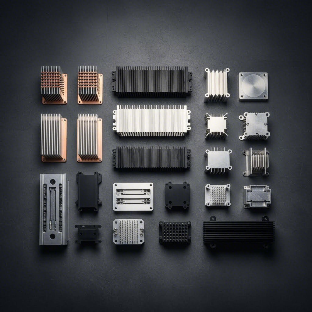
So far we've focused exclusively on extruded profiles—but here's the reality: extrusion isn't always the optimal choice. Depending on your power density, volume requirements, and budget constraints, alternative manufacturing methods might deliver better results. Understanding when to specify extrusion profiles versus bonded fin assemblies, skived heat sinks, or stamped solutions separates good thermal design from great thermal design.
Think of it this way: each manufacturing method represents a different point on the trade-off triangle of cost, performance, and design freedom. Leading heat sink manufacturers like Wakefield aluminum extrusions and Boyd heatsinks offer multiple fabrication technologies precisely because no single approach covers every application. Let's examine when each method makes sense.
Imagine you're cooling a 500W power inverter that generates intense, localized heat. Standard aluminum extruded profiles might struggle here—not because extrusion is flawed, but because physics imposes limits on achievable fin density through a die. Enter bonded fin construction.
Bonded fin heat sinks attach individual fins to a separate base plate using thermal epoxy, brazing, or mechanical fastening. According to industry specialists, this approach offers a critical advantage: you can mix materials. A copper base spreads heat rapidly from concentrated sources, while aluminum fins handle convective dissipation at reduced weight. This hybrid construction achieves thermal performance that pure aluminum extrusion profiles simply cannot match.
However, bonded construction comes with trade-offs. The thermal interface between fins and base introduces additional resistance—typically 0.02-0.05°C/W depending on bonding method. Assembly labor drives costs significantly higher than extrusion, making bonded fins practical only for high-value, high-power applications where performance justifies the premium.
What about applications where you need extremely high fin density but can't afford bonded construction costs? Skived heat sinks offer an intriguing middle ground.
Skiving uses a specialized blade to slice thin fins directly from a solid metal block, folding them upward without removing material. This process achieves fin densities impossible through extrusion—manufacturing experts report that skived designs can pack fins as close as 0.5mm apart. The integral connection between fins and base eliminates bonding resistance, delivering excellent thermal performance in a compact package.
The catch? Skiving works primarily with copper due to material ductility requirements, and production costs exceed extrusion for most volumes. Directional sensitivity also matters—skived fins perform best with airflow perpendicular to the fin direction.
Stamped heat sinks occupy the opposite end of the spectrum. Metal fins are stamped from sheet stock and soldered onto a base—fast, cheap, and highly automatable. For low-power applications under 20W, stamped solutions from any aluminum extrusion profiles catalog represent the most economical choice. But don't expect impressive thermal performance; the stamped-and-soldered interface limits heat transfer efficiency.
| Manufacturing Method | Thermal Performance | Low-Volume Cost | High-Volume Cost | Design Flexibility | Max Fin Density | Typical Power Range |
|---|---|---|---|---|---|---|
| Extruded | Low to High | Low | Very Low | Moderate (limited by die) | Medium | 5W - 200W |
| Bonded Fin | High | High | Medium-High | High (mixed materials) | High | 100W - 2000W+ |
| Skived | Medium to High | High | Medium | Moderate | Very High | 50W - 500W |
| Stamped | Low | Very Low | Very Low | Limited | Low | 1W - 25W |
| Die-Cast | Medium | High (tooling) | Low | Very High (complex 3D) | Medium | 10W - 150W |
| Forged | Medium | Medium | Low | Limited | Medium | 20W - 100W |
| CNC Machined | High | Very High | Very High | Highest | Very High | Any (prototypes) |
Ideal application scenarios for each manufacturing method:
Here's the practical decision framework: start with extrusion as your baseline. If standard aluminum extruded profiles from a manufacturer's catalog meet your thermal budget at acceptable cost, you're done. Only escalate to bonded, skived, or machined alternatives when extrusion demonstrably falls short—whether due to fin density limitations, power density beyond extrusion capabilities, or geometric constraints the die cannot achieve.
One final consideration before we explore application-specific selection: volume matters enormously. Die-cast and forged methods require substantial tooling investment but deliver extremely low per-unit costs at scale. For a 100,000-unit production run, the calculus differs dramatically from a 500-unit specialty order. Matching manufacturing method to production volume often matters as much as matching it to thermal requirements.
You now understand alloys, fin geometry, surface treatments, and manufacturing methods—but here's the question that really matters: which extrusion heat sink profile actually fits your application? A heat sink that performs brilliantly in an LED downlight might fail spectacularly in a power inverter. Different applications impose fundamentally different thermal constraints, and matching profile characteristics to those constraints separates successful designs from warranty nightmares.
Let's walk through the major application categories, examining what makes each unique and how to translate those requirements into profile specifications you can actually order from an aluminum extrusion profile catalog.
LED thermal management presents a deceptively simple challenge: keep junction temperatures below the threshold that guarantees your promised lumen maintenance. Sounds straightforward—until you realize that a 10°C increase in junction temperature can cut LED lifespan in half.
According to thermal engineering specialists, the key to LED heat sink selection lies in calculating your thermal resistance budget. Start with your LED's maximum junction temperature (typically 125°C for quality components), subtract your worst-case ambient temperature, then divide by power dissipation. This gives you the total allowable thermal resistance from junction to air.
Here's a worked example: imagine a 10W LED module with a maximum junction temperature of 125°C, operating in a ceiling cavity reaching 40°C worst-case. Your total thermal budget becomes (125 - 40) / 10 = 8.5°C/W. Subtract the known resistances—junction-to-case, board, and thermal interface material—and you're left with the heat sink requirement. If those internal resistances total 3°C/W, your heat sink must deliver 5.5°C/W or better.
Selection criteria for LED lighting applications:
When browsing an aluminum profile catalog for LED applications, look for profiles with moderate fin spacing (6-10mm for passive cooling) and generous base thickness for heat spreading from concentrated LED packages.
Power electronics operate in a different thermal universe. Where LEDs dissipate single-digit watts, IGBT modules and power transistors routinely generate hundreds of watts from compact semiconductor packages. The thermal challenge shifts from managing gradual lumen depreciation to preventing immediate catastrophic failure.
According to IGBT thermal management experts, excessive heat in power semiconductors increases electrical resistance, reduces switching efficiency, and can trigger thermal runaway—a destructive feedback loop where rising temperatures cause exponentially increasing heat generation. Effective cooling isn't just about longevity; it's about survival.
Power conversion applications demand heat sink profiles that can handle:
Telecommunications equipment represents a specialized subset with its own constraints. Base stations and network switches demand maximum cooling density in standardized rack-mount form factors. Here, every millimeter of fin height matters, and profiles must integrate seamlessly with chassis airflow patterns established by system-level thermal architects.
Regardless of application category, four variables determine whether a specific heat sink profile will meet your requirements: ambient temperature, available airflow, mounting constraints, and thermal budget.
Ambient temperature sets your starting point. As thermal design guidance notes, ambient assumptions typically range from 35-45°C when external air is available, rising to 50-60°C for enclosed components. Always design for worst-case conditions—a heat sink sized for 25°C ambient will overheat on hot summer days.
Available airflow determines fin spacing. Natural convection requires wider gaps (4mm minimum); forced convection allows tighter packing. When referencing alum extrusion shapes in supplier catalogs, note whether thermal resistance specifications assume natural or forced conditions—the difference can be 3-5x.
Mounting constraints dictate profile geometry. Limited height? Favor wider bases with shorter, denser fins. Restricted footprint? Accept taller fins with aggressive aspect ratios. Interface with specific semiconductor packages? Verify base dimensions accommodate your mounting pattern and thermal interface area.
Thermal budget ties everything together. Subtract all thermal resistances in the chain—junction-to-case, interface material, mounting contact—from your total allowable resistance. What remains is your heat sink target. Then find profiles in supplier catalogs that meet or exceed this requirement under your specific airflow conditions.
One practical tip for navigating selection: most heat sink suppliers publish thermal resistance curves showing performance versus airflow velocity. Use these curves to interpolate performance at your actual operating conditions rather than relying on single-point specifications that may not match your environment.
You've defined your thermal requirements, selected an alloy, and optimized your fin geometry—now comes the step that transforms your design into reality: partnering with the right manufacturer. Here's what many engineers discover too late: the gap between a theoretically optimal aluminum extrusion heat sink and a production-ready component often depends entirely on your manufacturing partner's capabilities. A supplier with limited equipment or expertise can force costly design compromises, while a full-service partner can actually enhance your original concept.
Think of custom heat sink manufacturers as more than fabricators—the best ones function as thermal engineering collaborators. They've seen thousands of designs, understand what works in production, and can identify potential issues before you've committed to expensive tooling. This collaborative relationship is especially valuable for heatsink extrusions, where the interplay between thermal performance, manufacturability, and cost creates complex trade-offs.
Imagine walking into a manufacturer's office with nothing but a thermal resistance target and a mounting envelope. How does that translate into a finished extruded heatsink? The journey typically follows four distinct phases.
Phase 1: Thermal Analysis and Concept Development
The process begins with defining what success looks like thermally. According to manufacturing specialists, experienced partners start by understanding your complete thermal chain—heat source characteristics, interface materials, airflow conditions, and ambient temperature limits. This information shapes initial profile concepts before any CAD work begins.
During this phase, your manufacturing partner should challenge assumptions and offer alternatives. Perhaps your initial concept calls for an aspect ratio that pushes extrusion limits—a knowledgeable supplier will suggest geometry modifications that maintain thermal performance while improving producibility.
Phase 2: Die Design and Engineering Review
Once the profile concept is finalized, die design begins. This isn't simply creating a negative image of your cross-section. Die engineers must account for metal flow dynamics, thermal expansion during extrusion, and wear patterns that affect long-term dimensional stability. As noted by industry experts, die costs typically range from $1,000 to $20,000 depending on complexity—a significant investment that underscores the importance of getting the design right before cutting steel.
Reputable manufacturers conduct thorough engineering reviews at this stage, verifying tolerances, surface finish requirements, and secondary operation compatibility. They'll flag potential issues like insufficient draft angles or problematic thin sections before committing to die production.
Phase 3: Prototyping and Validation
First article samples allow thermal testing before full production commitment. This validation step catches discrepancies between theoretical performance and real-world results—perhaps the actual thermal resistance runs 10% higher than calculated, or mounting flatness requires tighter control than standard tolerances provide.
Phase 4: Production Scaling
With validated prototypes in hand, production ramps up. Here's where manufacturing capacity becomes critical: a partner with multiple extrusion presses across various tonnage ratings can optimize your job for efficiency. Companies like Shengxin Aluminium, operating 35 extrusion presses ranging from 600T to 5500T, can match your profile complexity to the ideal press size—smaller presses for simpler geometries at lower cost, larger presses when aggressive aspect ratios demand higher extrusion force.
The extrusion itself represents only one step in creating a functional heat sink. Raw profiles emerge from the die in continuous lengths—they still need cutting, machining, and finishing before they're ready for assembly. This is where the distinction between a basic extruder and a full-service partner becomes apparent.
Consider secondary operations. Your heat sink likely needs mounting holes drilled and tapped, precise length cuts with tight tolerances, and perhaps milled pockets or counterbores for component clearance. According to thermal manufacturing experts, CNC fly-cutting can achieve flatness within 0.001 inch T.I.R.—essential for optimal thermal interface contact with semiconductor packages.
A manufacturer lacking in-house machining capabilities forces you to coordinate with separate vendors, adding logistics complexity and quality control challenges. Integrated operations under one roof streamline communication and accountability.
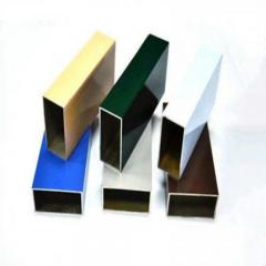
Surface treatment options matter equally. Different applications demand different finishes—anodizing for radiation enhancement and corrosion protection, powder coating for aesthetic housings, or specialized treatments for harsh environments. Shengxin Aluminium exemplifies comprehensive finishing capabilities, offering anodizing in custom colors (including champagne and rose gold), powder coating, PVDF, and micro-arc oxidation for superior durability. This range means your heat sink can receive optimal treatment without sourcing additional vendors.
When evaluating custom heat sink manufacturers, look for these key capabilities:
Industry leaders like Aavid Thermal (now part of Aavid Boyd) built their reputations by offering exactly this integrated approach—from thermal analysis through finished, tested components. For projects requiring custom 6063 aluminum profiles, finding a partner with similar end-to-end capabilities streamlines development and reduces risk.
One final consideration: experience matters. A manufacturer with decades of heat sink production has encountered—and solved—problems you haven't yet imagined. They know which fin geometries cause die wear, which alloy tempers extrude most consistently, and which surface treatments perform best under specific environmental conditions. This institutional knowledge, often spanning 30+ years at established suppliers, translates directly into better outcomes for your thermal management project.
You've journeyed through alloy properties, extrusion processes, fin optimization, surface treatments, manufacturing alternatives, and application-specific requirements. Now comes the moment of truth: turning all that knowledge into a concrete selection decision for your project. Rather than leaving you with scattered insights, let's consolidate everything into a practical framework you can apply immediately—whether you're sourcing stock aluminum extrusion profiles or developing a fully custom solution.
Think of heat sink selection as a sequential filtering process. Each decision narrows your options until you arrive at the profile that best balances thermal performance, manufacturability, and cost for your specific application.
Follow this structured approach to systematically work through your thermal management requirements:
Before committing to custom tooling, check whether existing stock aluminium extrusion profiles from supplier catalogs meet your requirements. Standard profiles often satisfy thermal needs at lower cost and faster lead times than custom dies. Only invest in custom development when stock options demonstrably fall short.
With your requirements defined and selection criteria established, you're ready to engage manufacturers. Here's what separates successful projects from frustrating ones: choosing a partner whose capabilities align with your project's complexity.
For projects requiring custom 6063 aluminum profiles with integrated secondary operations, Shengxin Aluminium offers comprehensive manufacturing support built on over 30 years of extrusion experience. Their facility houses 35 extrusion presses spanning 600T to 5500T capacity—meaning your profile gets matched to optimal equipment regardless of complexity. In-house CNC machining centers handle drilling, tapping, and precision cutting, while surface treatment options including custom-color anodizing, powder coating, PVDF, and micro-arc oxidation ensure your heat sink arrives ready for assembly.
This end-to-end approach—from die development through mass production—eliminates the coordination headaches of managing multiple vendors while maintaining quality control under one roof.
The most critical principle in heat sink selection: match your profile to your cooling method first, optimize geometry second, and fine-tune alloy and finish last. A perfectly specified alloy cannot compensate for fin spacing that chokes airflow, nor can premium surface treatment rescue a geometry that ignores convection fundamentals.
Whether you're designing LED lighting fixtures, power electronics enclosures, or telecommunications equipment, the framework remains consistent. Define thermal requirements mathematically, select geometry based on airflow conditions, and partner with aluminum heat sink suppliers capable of translating your specifications into production reality.
Ready to explore your options? Browse an extruded aluminum shapes catalog to identify standard profiles matching your thermal resistance targets, or reach out to full-service manufacturers for custom solutions when stock options fall short. Your thermal management success starts with applying the systematic approach outlined throughout this guide—and ends with a heat sink profile that keeps your components cool, reliable, and performing at their best.
The optimal aluminum alloy depends on your specific application requirements. For most heat sink applications, 6063 aluminum is the preferred choice due to its excellent thermal conductivity of 201 W/m·K, superior extrudability for complex fin geometries, and cost-effectiveness. However, 6061 aluminum offers higher tensile strength (up to 240 MPa) making it ideal when the heat sink must serve dual structural purposes or withstand mechanical stress. Pure aluminum alloys like 1050 provide the highest thermal conductivity at 229 W/m·K but lack the mechanical properties needed for practical heat sink applications. When partnering with manufacturers like Shengxin Aluminium, you can specify custom 6063 aluminum profiles with optimized temper conditions for your exact thermal and mechanical requirements.
Extruded aluminum heat sink material refers to aluminum alloy profiles manufactured by forcing heated aluminum billets through specially designed steel dies. The most common material is 6063-T5 aluminum, chosen for its balance of thermal conductivity, extrudability, and structural integrity. The extrusion process heats aluminum billets to 400-500°C before pushing them through the die to create continuous profiles with integrated fins and base. This manufacturing method produces heat sinks with excellent surface finishes, consistent dimensions, and cost-effective production at scale. Alternative alloys include 6061 for higher strength applications and 6060 for thin-walled profiles, with each offering different thermal and mechanical trade-offs.
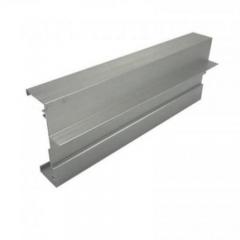
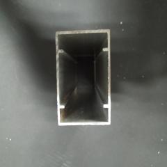
Aluminum extrusion profiles for heat sinks come in three primary forms: solid, hollow, and semi-hollow configurations. Solid profiles feature continuous fin structures integrated with a base plate, ranging from simple flat-back designs to complex multi-fin geometries. Hollow profiles incorporate internal channels for liquid cooling applications or weight reduction. Semi-hollow profiles combine elements of both, often featuring enclosed spaces within the fin structure. Beyond structural classification, heat sink profiles vary by fin configuration including straight fins, pin fins, and cross-cut designs. Each type serves specific cooling requirements—straight fins excel in unidirectional airflow, while pin fins provide omnidirectional performance for natural convection applications.
Selecting the right heat sink for LED lighting requires calculating your thermal resistance budget based on maximum junction temperature, ambient conditions, and power dissipation. Start with your LED's maximum junction temperature (typically 125°C), subtract worst-case ambient temperature, and divide by wattage to determine total allowable thermal resistance. Then subtract internal resistances from junction-to-case and interface materials to find your heat sink requirement. For passive LED fixtures, choose profiles with 6-10mm fin spacing to accommodate natural convection. Consider anodized finishes to boost thermal radiation in sealed enclosures. Account for mounting orientation since horizontal ceiling-mounted fins lose 25-40% efficiency compared to vertical orientation. Full-service manufacturers offer end-to-end support from thermal analysis through production.
Choose extruded heat sinks when cost efficiency, moderate thermal performance, and design simplicity are priorities. Extrusion excels for power ranges of 5-200W, offering the lowest per-unit cost at production volumes. Select bonded fin assemblies when handling high-power applications (100-2000W+) requiring mixed materials like copper bases with aluminum fins for superior heat spreading. Opt for skived heat sinks when maximum fin density matters in compact spaces, achieving spacing as tight as 0.5mm—ideal for dense server CPUs and telecom equipment at 50-500W. Stamped heat sinks suit low-power applications under 25W where cost trumps performance. Your decision should balance power density, production volume, and budget constraints against thermal requirements.



 خدمة الإنترنت
 0086 136 3563 2360
 sales@sxalu.com
 +86 136 3563 2360
 العربية
 English
 français
 Deutsch
 русский
 español
 português
 ไทย
ไทย Việt
Việt Українська