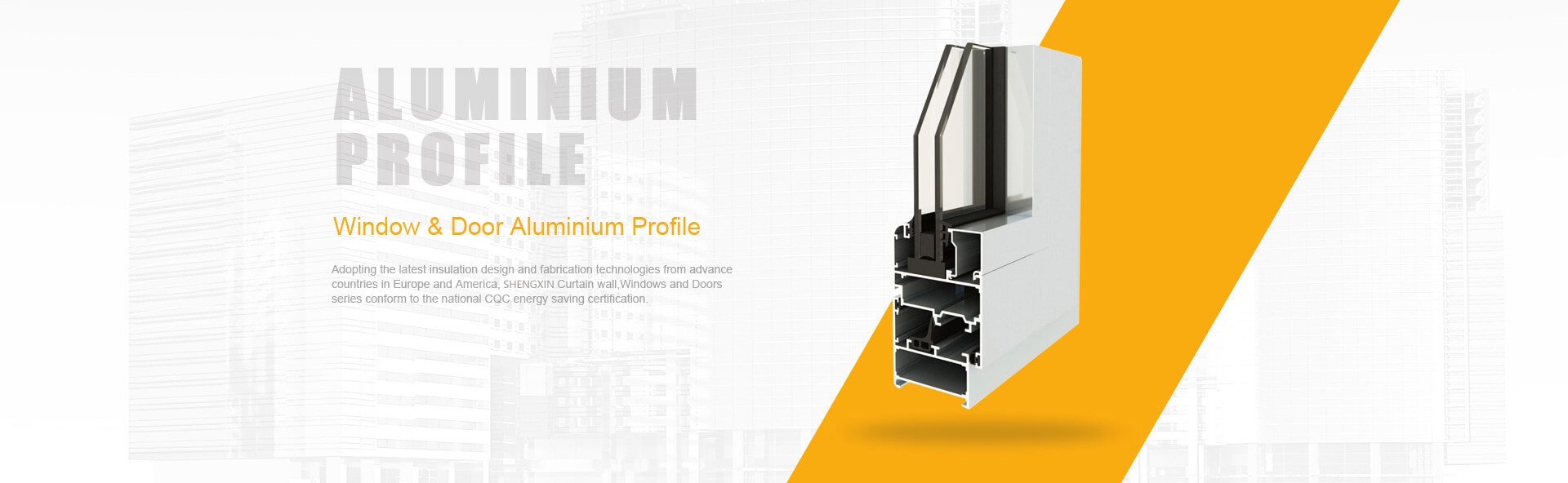
Ever wondered how manufacturers create those intricate aluminum profiles you see in window frames, heat sinks, and aircraft components? The answer lies in a remarkably elegant process called aluminum extrusion. Whether you're a seasoned engineer or just beginning your aluminum extrusion design guide journey, understanding these fundamentals will transform how you approach profile design.
Aluminum extrusion is a manufacturing process where heated aluminum alloy is forced through a shaped die opening under high pressure, creating continuous profiles with uniform cross-sections that match the die's geometry.
This aluminium extrusion definition captures the essence of what makes this process so valuable across industries. Think of it like squeezing toothpaste through a tube - except you're working with metal heated to around 800-925°F (427-496°C), and the "tube opening" is a precision-engineered steel die.
Unlike casting, machining, or rolling, extrusion offers a distinctive combination of benefits that no other metal-forming method can match. You'll notice that extruded profiles emerge as continuous lengths with consistent cross-sectional geometry - perfect for applications requiring long, uniform components.
Consider these unique advantages:
The aluminium extrusion meaning extends beyond just shaping metal - it represents a design philosophy where form and function integrate seamlessly from the earliest concept stages.
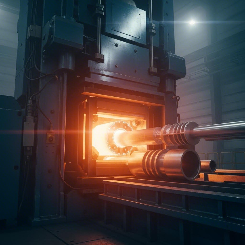
Imagine you're watching the extrusion process unfold. First, a cylindrical aluminum billet - typically 6 to 9 inches in diameter - enters a container and gets heated to its optimal plasticity temperature. At this point, the aluminum becomes soft enough to flow but maintains enough structural integrity to hold its shape upon cooling.
Here's where hydraulic pressure enters the picture. A powerful ram applies anywhere from 100 to 15,000 tons of force, pushing the softened aluminum toward the die. As pressure builds, the metal has nowhere to go except through the die's precisely machined opening. The aluminum flows through channels called "ports" if it's a hollow profile, reuniting on the other side of the die in the mandrel area before emerging as your finished shape.
The profile emerges at speeds ranging from a few feet per minute for complex shapes to over 200 feet per minute for simple solid profiles. Immediately after exiting the die, the extrusion travels along a run-out table where cooling systems - typically water quench or forced air - rapidly reduce its temperature to lock in the desired metallurgical properties.
Understanding this process helps you make smarter design decisions. When you know that metal must flow evenly through every section of your profile, you'll instinctively design with balanced wall thicknesses and smooth transitions. This aluminum extrusion design guide principle alone prevents countless manufacturing headaches before they occur.
Now that you understand how aluminum flows through a die, here's the next critical question: which aluminum alloy should you specify? This decision impacts everything from manufacturing feasibility to long-term performance. Selecting the wrong alloy can mean profiles that crack during extrusion, corrode prematurely in service, or simply cost more than necessary.
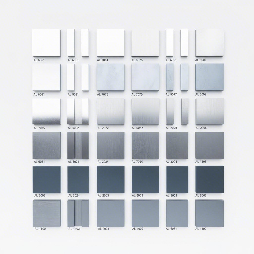
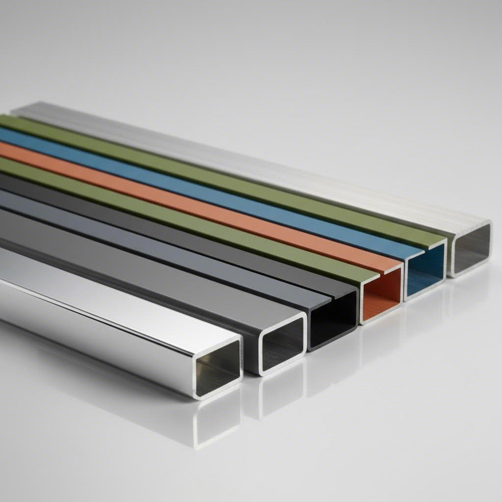
Aluminum extrusion design begins with understanding that pure aluminum rarely meets engineering demands. Instead, manufacturers blend aluminum with elements like magnesium, silicon, copper, and zinc to create alloys with enhanced properties. Each alloy series offers distinct characteristics suited to specific aluminium extrusion parts and applications.
| Alloy Series | Typical Applications | Strength Level | Corrosion Resistance | Extrudability | Weldability |
|---|---|---|---|---|---|
| 1000 (Pure Al) | Electrical conductors, chemical equipment | Low | Excellent | Excellent | Excellent |
| 2000 (Al-Cu) | Aerospace structures, aircraft skins | Very High | Poor | Poor | Limited |
| 3000 (Al-Mn) | Heat exchangers, cooking utensils | Low-Medium | Good | Good | Good |
| 5000 (Al-Mg) | Marine components, pressure vessels | Medium-High | Excellent | Moderate | Excellent |
| 6000 (Al-Mg-Si) | Architectural, structural, automotive | Medium-High | Good | Excellent | Good |
| 7000 (Al-Zn) | Aerospace, military, high-stress parts | Highest | Moderate | Poor-Moderate | Limited |
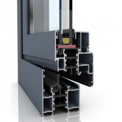
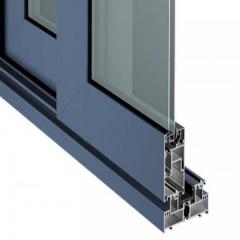
If you're designing architectural profiles, window frames, door systems, or general structural components, the 6000 series will likely become your go-to choice. These alloys combine magnesium and silicon to create heat-treatable materials with an exceptional balance of properties.
The 6063 alloy stands as the most popular choice for aluminum extrusions, particularly when thin walls and aesthetic finishes matter. Why does 6063 dominate architectural applications? It offers outstanding extrudability, meaning it flows smoothly through complex die geometries without tearing or distorting. You'll also appreciate its excellent response to anodizing, producing uniform, attractive surface finishes.
When your aluminum extrusion design demands higher strength than 6063 provides, consider these alternatives within the 6000 family:
The engineering rationale here is straightforward: 6000 series alloys achieve their strength through precipitation hardening during heat treatment. The T5 and T6 tempers you'll commonly specify represent different aging processes that develop the alloy's final mechanical properties after extrusion.
What happens when standard architectural alloys simply can't deliver the strength your application demands? Aerospace, military, and high-performance applications often require stepping outside the 6000 comfort zone into the 2000 and 7000 series.
The 7075 grade ranks as the strongest commercially available aluminum alloy, actually surpassing many mild steel grades in strength. This remarkable capability comes from zinc as the primary alloying element, combined with magnesium and copper. Aircraft structural components, highly stressed fittings, and military hardware frequently specify 7075 when maximum strength-to-weight ratio is non-negotiable.
However, specifying aerospace alloys involves accepting significant trade-offs:
The 2024 alloy deserves special mention for applications demanding high fatigue resistance alongside strength. Aircraft skins and structural components frequently use 2024 where repeated stress cycles occur. Just remember that aluminum extrusion with iron-containing alloys or high-copper formulations often requires additional surface protection strategies.
Sounds complex? Let's simplify the selection process by focusing on your application's primary requirements:
For marine and chemical environments: The 5000 series alloys with their magnesium content deliver exceptional corrosion resistance. While less extrudable than 6000 series options, they excel where saltwater or aggressive chemicals threaten material integrity.
For electrical applications: The 1000 series (essentially pure aluminum) offers maximum electrical conductivity. Alloy 1050 represents a common choice for bus bars and electrical conductors where current-carrying capacity trumps mechanical strength.
For cost-sensitive projects: The 6000 series offers the best value proposition - readily available, easily extruded, and moderately priced. Working with an experienced aluminum extrusion manufacturer helps you identify where premium alloys genuinely add value versus where standard grades perform adequately.
When evaluating aluminium extrusion parts for your project, consider that complex geometries and thin walls favor alloys like 6063 or 6360 - their superior flow characteristics ensure uniform shapes with minimal distortion. Conversely, if your profile features thick, simple sections requiring maximum strength, 6061 or even 7000 series alloys become viable options despite their reduced extrudability.
The alloy you select today determines not only manufacturing success but also finishing options, assembly methods, and long-term service performance. With your alloy decision made, the next crucial step involves understanding the dimensional constraints and design parameters that transform your concept into a manufacturable profile.
You've selected the perfect alloy for your application - now comes the moment of truth. Will your profile actually extrude successfully? The difference between a manufacturable design and one that causes endless production headaches often comes down to understanding aluminum extrusion tolerances and dimensional constraints. Let's explore the essential aluminium extrusion design guidelines that separate experienced designers from beginners.
Imagine forcing soft aluminum through a steel die opening that's barely thicker than a credit card. That's essentially what happens when you specify ultra-thin walls without considering the physical limits of the extrusion process. Wall thickness represents the single most critical parameter in your aluminum extrusion design guidelines.
The minimum wall thickness you can specify depends directly on your profile's circumscribing circle diameter. According to Bonnell Aluminum's technical guidelines, here's what you need to know:
| Circumscribing Circle (inches) | Solids & Semihollows (min.) | Class 2 Hollows (min.) |
|---|---|---|
| 0.5 to under 2 | 0.040" | 0.055" |
| 2 to under 3 | 0.045" | 0.062" |
| 3 to under 4 | 0.050" | 0.078" |
| 4 to under 5 | 0.062" | 0.094" |
| 5 to under 6 | 0.078" | 0.110" |
| 6 to under 8 | 0.094" - 0.110" | 0.125" - 0.140" |
| 8 to under 12 | 0.125" - 0.172" | 0.156" - 0.220" |
Why do hollow profiles require thicker walls than solid shapes? The answer lies in the die construction. Hollow profiles use porthole dies where the aluminum must flow around mandrel supports and reweld on the exit side. This more complex flow path demands additional material thickness to maintain structural integrity.
Here's a critical rule that many designers overlook: adjacent wall thickness ratios should never exceed 2:1. When you design a profile with dramatically different thicknesses side by side, the aluminum flows unevenly through the die. The thicker sections cool more slowly than thin areas, creating internal stresses that lead to warping, twisting, and dimensional instability.
The circumscribing circle - often abbreviated as "cc" in industry shorthand - represents the smallest circle that completely encloses your profile's cross-section. This single measurement determines press selection, die complexity, and ultimately, your project's feasibility.
Think of it this way: larger circumscribing circles require larger extrusion presses with greater tonnage capacity. A profile with a 10-inch cc demands significantly more force to push through the die than one measuring just 3 inches. Modern high-capacity presses can handle architectural-quality extrusions exceeding 16 inches in circumscribing circle diameter.
The circumscribing circle also helps calculate die difficulty factor - a key predictor of manufacturing challenges:
When developing your design, keep these aluminum extrusion tolerances in mind. The Aluminum Association publishes standard tolerance charts covering metal dimensions, space dimensions, straightness, twist, and flatness. For applications where profiles must mate precisely with other components, understanding tolerance classes becomes essential for successful downstream assembly.
Sharp corners are the enemy of successful extrusion. When aluminum flows through a die, it naturally wants to round off any abrupt transitions. Forcing metal into perfectly sharp 90-degree corners creates stress concentrations that accelerate die wear and leave surface marks on your finished profiles.
What corner radii should you specify? Consider these aluminum extrusion design guidelines:
Draft angles present another consideration, particularly for profiles requiring secondary finishing operations. While extrusion itself doesn't require draft angles like casting or molding, adding slight tapers (typically 1-3 degrees) can improve die release and facilitate powder coating or anodizing coverage on complex geometries.
Shape classification also influences your design constraints. Profiles fall into three categories:
Symmetry deserves special attention. Balanced profiles with symmetrical cross-sections extrude more consistently than asymmetrical designs. When asymmetry is unavoidable, work with your extrusion partner to optimize die bearing lengths and flow balancing - topics we'll explore in the next section on tooling engineering.
Here's a reality check that catches many designers off guard: your beautifully optimized profile means nothing if the die can't produce it reliably. Aluminium extrusion tooling represents the critical bridge between your CAD model and physical reality. Understanding how dies work - and what makes them succeed or fail - transforms you from a profile designer into a true extrusion engineer.
Every custom aluminum extrusion catalog starts with tooling investment. Unlike injection molding where molds can cost tens of thousands of dollars, extrusion dies remain remarkably affordable - typically ranging from $500 to $3,000 for most profiles. However, this accessible entry point doesn't mean tooling decisions are trivial. The die's design directly impacts your per-piece costs, quality consistency, and production speed for years to come.
Think about what happens inside an extrusion die. Aluminum at 900°F flows under immense pressure through precision-machined steel passages. The more complex those passages, the harder the die works - and the faster it wears out.
Die complexity translates directly into costs through several mechanisms:
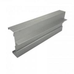
What determines complexity? The extruded aluminum shapes catalog your manufacturer provides offers clues. Simple solid shapes like angles, channels, and rectangular tubes represent low-complexity tooling. As you add features - internal ribs, asymmetrical hollows, varying wall thicknesses, tight tolerances - complexity escalates.
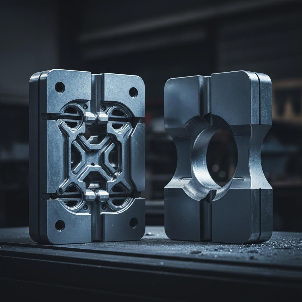
The fundamental distinction in aluminium extrusion tooling comes down to whether your profile contains enclosed voids. This classification determines not just die construction but also minimum wall thicknesses, tolerance capabilities, and cost structures.
Solid dies (also called flat dies) feature a single opening machined directly into a steel plate. Aluminum flows straight through without splitting and rejoining. These dies offer maximum simplicity - faster to manufacture, easier to correct, and longest-lasting in production.
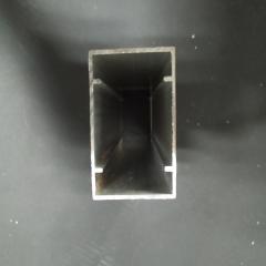
Hollow dies (porthole or bridge dies) handle profiles with completely enclosed voids - think tubes, multi-cell sections, and complex hollow shapes. Here's where things get interesting: the die must split incoming aluminum into multiple streams, flow it around mandrel supports, then reweld the streams back together before the profile exits. This welding happens under pressure and temperature inside the die itself.
When should you choose each type?
Smart designers don't just create manufacturable profiles - they create profiles that dies love producing run after run. Die longevity directly affects your long-term economics since replacement tooling and production interruptions add costs that rarely appear in initial quotes.
Bearing length represents your primary tool for controlling metal flow. The bearing is the parallel land area where aluminum makes final contact with the die before emerging. Longer bearings slow flow; shorter bearings speed it up. Die makers adjust bearing lengths across different sections of your profile to ensure uniform exit velocity - a process called flow balancing.
Here's how you can optimize your designs for better die performance:
The die development workflow from your initial concept to production-ready tooling follows a structured path:
Expect die corrections on complex profiles - they're normal, not failures. Even experienced die designers can't perfectly predict how aluminum will flow through novel geometries. The correction process typically involves one to three iterations before achieving production-ready status.
With your tooling considerations addressed, another crucial factor awaits: how will your profiles be finished? Surface treatment selection actually influences tooling decisions you're making right now - a connection we'll explore next.
Here's something that surprises many designers: the finish you want on your completed profile should influence decisions you make at the very beginning of your project. Surface treatments aren't just cosmetic afterthoughts - they interact with alloy selection, wall thickness choices, and geometric details in ways that can make or break your final product quality.
Whether you're aiming for the brilliant metallic sheen of anodized architectural components or the vibrant colors of powder-coated industrial equipment, understanding how finishes affect upstream design decisions puts you ahead of competitors who treat finishing as someone else's problem.
| Finishing Method | Durability Rating | Relative Cost | Color Options | Best Applications |
|---|---|---|---|---|
| Clear Anodizing | Excellent | Low-Medium | Natural aluminum tones | Architectural, electronics, decorative |
| Color Anodizing | Excellent | Medium | Limited (blacks, bronzes, golds) | Architectural accents, consumer products |
| Powder Coating | Very Good | Medium | Virtually unlimited | Industrial, outdoor furniture, automotive |
| PVDF/Kynar | Superior | High | Wide range, excellent UV stability | Architectural facades, coastal environments |
| Mechanical Finishing | Moderate | Low | Natural metallic | Industrial, hidden components |
| Specialty (Micro-arc, etc.) | Exceptional | High-Very High | Limited | Extreme wear, high-temperature applications |
Anodizing doesn't simply coat your aluminum - it transforms the surface layer into aluminum oxide, creating an integral part of the metal rather than an applied coating. This electrochemical process produces exceptional hardness, corrosion resistance, and that distinctive aluminum aesthetic architects love.
But here's the catch: anodizing reveals every flaw in your base material and extrusion quality. Die lines, grain structure variations, and alloy inconsistencies that might hide under paint become prominently visible after anodizing. Your alloy choice matters tremendously here.
Consider these alloy-anodizing interactions:
Wall thickness also affects anodizing outcomes. Standard architectural anodizing adds approximately 0.0005" to 0.001" per surface - half penetrating into the base metal, half building outward. For precision-fit components, account for this dimensional change in your original design. Thin-walled sections may also show more temperature-related distortion during the anodizing bath process.
When you need vibrant colors, exact color matching, or heavy-duty protection, powder coating delivers where anodizing can't. Electrostatically applied dry powder melts and cures into a uniform coating typically 2-4 mils thick - substantially heavier than anodized finishes.
Profile geometry directly impacts powder coating success. Think about how charged powder particles travel through electric fields to reach your profile's surfaces. Complex geometries create challenges:
Unlike anodizing, powder coating is more forgiving of alloy variations. You can successfully powder coat 2000 and 7000 series aerospace alloys that anodize poorly. However, surface preparation becomes critical - proper cleaning, chromate or chrome-free pretreatment, and controlled environments ensure adhesion and longevity.
What happens when standard anodizing or powder coating simply won't survive your application? Specialty finishes address extreme requirements - but they come with cost premiums and additional design constraints.
PVDF (Polyvinylidene Fluoride) coatings - often sold under the Kynar brand - deliver exceptional UV resistance and color retention. Architectural projects with multi-decade service life expectations frequently specify PVDF for exposed facades. These fluoropolymer coatings resist chalking, fading, and chemical attack far longer than standard powder coatings, making them ideal for coastal, industrial, or high-pollution environments.
Hard anodizing creates oxide layers up to 0.004" thick with hardness approaching that of tool steel. Wear surfaces, sliding components, and military applications benefit from this enhanced treatment. However, hard anodizing produces only dark gray to black colors and requires accounting for significant dimensional buildup.
Micro-arc oxidation (also called plasma electrolytic oxidation) generates ceramic-like surface layers with exceptional hardness and thermal resistance. While expensive, this process creates surfaces that outperform conventional anodizing in extreme wear and high-temperature applications.
The key insight across all finishing methods? Decisions made during profile design - alloy selection, wall thickness, corner geometry, surface quality requirements - cascade directly into finishing outcomes and costs. By specifying finishes early and designing with them in mind, you avoid costly rework and ensure your profiles perform as beautifully as they look.
With finishing strategies established, modern designers increasingly rely on digital tools to validate their choices before committing to tooling. Let's explore how CAD integration and simulation software are transforming the extrusion design workflow.
Here's a question that increasingly shapes purchasing decisions across industries: how sustainable is your aluminum extrusion design? Beyond performance specifications and cost calculations, environmental impact now influences material selection, finishing choices, and end-of-life planning. The good news? Aluminum offers inherent sustainability advantages that few competing materials can match - if you design with lifecycle thinking from the start.
Aluminum is infinitely recyclable without degradation in quality, and recycling aluminum requires only 5% of the energy needed to produce primary aluminum from ore.
This remarkable recyclability makes sustainable aluminum extrusion more than marketing language - it's engineering reality. Your aluminium extrusion design guide decisions today directly influence environmental outcomes decades from now.
When you design recyclable aluminum profiles, you're not just creating components - you're creating future raw materials. However, not all extrusion designs recycle equally well. Several factors determine how efficiently your profiles can re-enter the aluminum stream at end-of-life.
Consider these design strategies that enhance recyclability:
Interestingly, the alloy you specify affects recycling economics. The 6000 series alloys dominating architectural and industrial applications recycle efficiently into similar products. Aerospace-grade 2000 and 7000 series materials, while recyclable, often get downcycled into less demanding applications due to their specialized chemistry.
Not all aluminum carries the same carbon burden. Primary aluminum production - extracting metal from bauxite ore through electrolysis - ranks among the most energy-intensive industrial processes. The carbon footprint varies dramatically based on the electricity source powering smelters.
When environmental performance matters to your project, consider these factors:
Your finishing choices also carry environmental implications. Water-based powder coating systems and chrome-free pretreatments represent lower-impact alternatives to traditional processes. When specifying finishes, ask manufacturers about their environmental management practices and waste treatment capabilities.
Sustainable design extends beyond recyclability and carbon footprint to encompass the entire product lifecycle. How long will your extrusion serve its intended purpose? What maintenance requirements will it generate? How does its performance compare to alternative materials over decades of service?
Aluminum excels in lifecycle assessments for several reasons:
When documenting your designs according to any standard aluminum extrusion profiles pdf or specification package, consider including sustainability notes. Specify alloy recyclability, recommended disassembly procedures, and environmental certifications your profiles can support. This documentation becomes increasingly valuable as building codes, procurement policies, and consumer preferences shift toward verified sustainable materials.
The integration of sustainability into your design process doesn't require sacrificing performance or dramatically increasing costs. Often, sustainable choices align with good engineering practice - efficient material use, appropriate alloy selection, and durable finishes that extend service life. With environmental considerations addressed, the next step involves leveraging digital tools to validate and optimize your designs before committing to physical tooling.
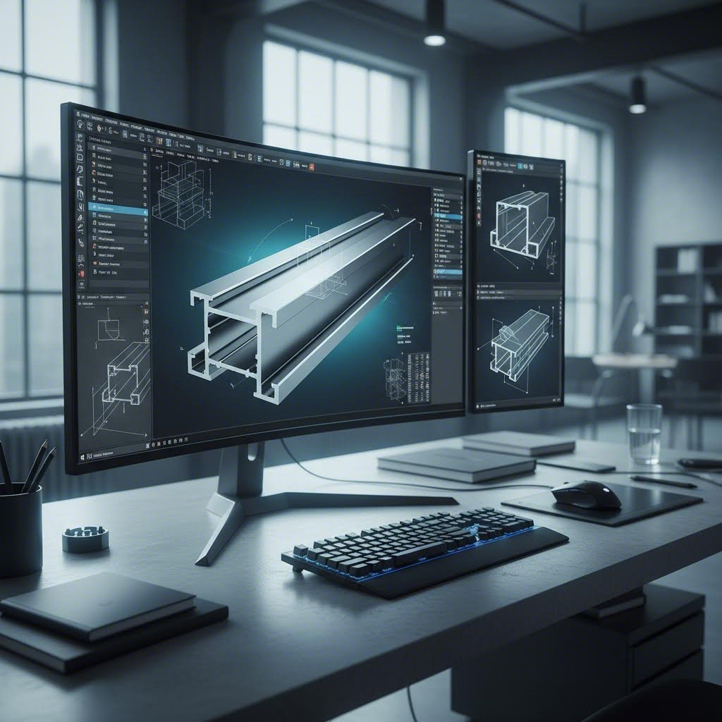
You've designed your profile on paper - or at least in your head. Now comes the moment when your concept must translate into digital files that manufacturers can actually use. Modern aluminum extrusion CAD files do far more than simply document geometry; they communicate intent, establish tolerances, and enable simulations that catch problems before expensive tooling gets cut.
Whether you're working in SolidWorks, AutoCAD, Fusion 360, or specialized extrusion profile design software, understanding how your digital workflow connects to manufacturing reality separates smooth projects from frustrating back-and-forth cycles.
Creating aluminum extrusion 3D models requires thinking differently than designing machined or molded parts. Your CAD model represents a continuous cross-section that extends infinitely in one direction - fundamentally different from the complex three-dimensional forms other manufacturing methods produce.
Here are essential CAD considerations for extrusion design that will streamline your manufacturer communications:
When designing aluminum extrusion assembly components where multiple profiles mate together, tolerance stack-up becomes critical. Most CAD software includes tolerance analysis tools that calculate cumulative effects across assembled parts. Use these tools to verify fit before submission - discovering interference issues after tooling exists costs far more than virtual validation.
Imagine sending your manufacturer a file they can't open - or worse, one that opens but loses critical dimension data. File format selection directly impacts how accurately your design intent transfers to the production floor.
What formats do extrusion manufacturers prefer? For profile cross-sections and complex geometries, prioritize these options:
Avoid sending only proprietary native files unless you've confirmed your manufacturer uses the same software version. A SolidWorks 2024 file won't open properly in an older version, and format conversion can introduce subtle geometry errors.
Your submission package should include more than just geometry files. According to industry best practices for extrusion CAD submissions, always provide:
What if you could watch aluminum flow through your die before the die even exists? Modern simulation tools make this possible, revealing potential problems when fixes cost nothing more than design revisions.
Flow simulation software - typically using Finite Element Method (FEM) or Computational Fluid Dynamics (CFD) approaches - predicts how heated aluminum will behave as it's forced through your profile geometry. For challenging hollow sections or thin fins, simulation can tune feeder plate design, bearing lengths, and pocket geometry before cutting steel.
These digital validation tools help you identify:
Not every project justifies simulation investment. Simple solid profiles with balanced geometry rarely surprise experienced die designers. However, when you're pushing boundaries - ultra-thin walls, complex hollows, asymmetrical shapes, or tight tolerances - simulation provides insurance against costly tooling iterations.
Some manufacturers offer simulation as part of their design-for-manufacturability review. Others work with specialized software providers. When risk is high, consider requesting a pilot die with simplified features to validate flow and straightness before committing to final tooling.
Digital workflows don't replace collaboration with experienced extrusion engineers - they enhance it. The most successful projects combine sophisticated CAD tools with early manufacturer engagement, creating feedback loops that refine designs before tooling investment. With your digital files prepared and validated, the next step involves understanding how to partner effectively with extrusion manufacturers to bring your designs to production reality.
You've optimized your profile geometry, selected the ideal alloy, and prepared production-ready CAD files. Now comes the human element - actually working with custom aluminum extrusion manufacturers to transform your design into physical reality. This aluminum extrusion project workflow phase determines whether your project glides smoothly toward production or stumbles through miscommunications and delays.
Successful aluminum extrusion supplier selection goes beyond comparing price quotes. The manufacturer you choose becomes a technical partner whose expertise, communication style, and production capabilities directly shape your project outcomes. Let's explore how to build partnerships that deliver results.
Think of your submission package as a first impression that sets the tone for your entire relationship. A complete, well-organized package signals professionalism and helps manufacturers provide accurate quotes faster. An incomplete submission triggers back-and-forth emails that delay your timeline.
Your comprehensive design submission should include:
Don't underestimate the value of application context. When manufacturers understand your end use, they can recommend alloy alternatives, suggest design modifications that improve extrudability, or flag potential issues with your finishing specifications. According to industry guidance on manufacturer selection, experienced partners familiar with your industry will be better equipped to meet your specific needs.
Here's where many projects go sideways: assuming your manufacturer interprets tolerance requirements the same way you do. Standard Aluminum Association tolerances cover most general applications, but precision assemblies often demand tighter specifications - and those need explicit communication.
When specifying tolerances, consider these best practices:
Your RFQ should include tolerance expectations alongside technical specifications to enable apples-to-apples quote comparisons. Manufacturers who understand your precision requirements upfront can price accordingly and identify potential challenges before tooling begins.
Understanding the typical aluminum extrusion project workflow helps you set realistic expectations and plan your timeline effectively. While specific durations vary by manufacturer capacity and project complexity, here's what the journey typically looks like:
For projects requiring rapid turnaround, domestic manufacturers offer significant advantages. According to industry analysis, domestic extruders routinely turn around dies and production runs in three to eight weeks, with repeat orders achieving lead times as low as two weeks. Offshore sourcing extends these timelines considerably due to ocean freight averaging 32-52 days depending on destination.
When evaluating extrusion manufacturer partnership options, production capability matters as much as quoted prices. Consider whether your partner has the press capacity to handle your profile's circumscribing circle and annual volumes. For example, Shengxin Aluminium operates 35 extrusion presses ranging from 600T to 5500T capacity, providing flexibility to match your profile requirements with appropriate equipment. Their end-to-end support - from die development through mass production, CNC machining, and surface treatments including anodizing, powder coating, PVDF, and micro-arc oxidation - illustrates the comprehensive capabilities that streamline complex projects.
Quality control practices deserve careful scrutiny during aluminum extrusion supplier selection. Reputable manufacturers perform quality checks at various stages of the extrusion process to ensure products meet industry standards. Ask about ISO certifications, in-process inspection procedures, and how non-conforming material is handled. The cost of inadequate quality control far exceeds any savings from lower piece prices.
Communication frequency and responsiveness also signal partnership quality. How quickly does the manufacturer respond to technical questions? Do they proactively share updates on production status? Can you visit their facility to observe operations? These soft factors often differentiate good suppliers from great partners.
With your manufacturing partnership established, the final step involves assembling the resources and checklists that ensure your designs succeed from first article through ongoing production.
You've journeyed through alloy selection, dimensional constraints, tooling engineering, surface treatments, and manufacturer partnerships. Now comes the practical question every designer faces: what resources should you keep at your fingertips, and what steps will transform your aluminum extrusion design checklist knowledge into production-ready profiles?
This final section provides the actionable references and verification tools you need to move confidently from concept to completed parts. Whether you're finalizing your first custom profile or refining designs for your hundredth project, these resources synthesize best practices from North American, European, and Australian extrusion engineering standards into globally applicable guidance.
Building a comprehensive extrusion design reference guide requires access to authoritative technical documents. The following publications should anchor your design library:
Beyond formal standards, manufacturer-specific aluminum profile design resources prove invaluable. Most established extruders publish design guides, tolerance charts, and alloy selection tools tailored to their capabilities. Request these during your initial supplier conversations - they often contain practical insights that formal standards don't address.
Before sending your design to potential manufacturing partners, verify every critical parameter. This aluminum extrusion design checklist consolidates the essential verification points covered throughout this manual:
Taking time to verify each item prevents costly revisions and accelerates your path to production-ready tooling.
Aluminum extrusion technology continues evolving. New alloys enter the market, simulation tools grow more sophisticated, and sustainability requirements reshape material selection criteria. Staying current requires ongoing engagement with extrusion engineering standards and industry developments.
Consider these approaches for continued learning:
Ready to move from design to production? Your next steps depend on where you are in the project lifecycle:
The knowledge you've gained through this extrusion design reference guide positions you to create profiles that are manufacturable, cost-effective, and precisely suited to your applications. Remember that successful aluminum extrusion design combines technical knowledge with collaborative partnerships - the best profiles emerge when designers and manufacturers work together from the earliest concept stages through final production.
Aluminum extrusion is a manufacturing process where heated aluminum alloy (800-925°F) is forced through a precision-engineered steel die under high hydraulic pressure ranging from 100 to 15,000 tons. The softened aluminum flows through the die opening, emerging as a continuous profile with uniform cross-sectional geometry. Profiles exit at speeds from a few feet per minute for complex shapes to over 200 feet per minute for simple solids, then undergo rapid cooling via water quench or forced air to lock in desired metallurgical properties.
Alloy selection depends on your application requirements. The 6063 alloy is ideal for architectural profiles requiring excellent extrudability and anodizing response. For higher strength structural applications, 6061 offers better mechanical properties with good weldability. Aerospace applications requiring maximum strength may need 7075 or 2024 alloys, though these have reduced extrudability and corrosion resistance. Marine environments benefit from 5000 series alloys with superior corrosion resistance, while electrical applications favor 1000 series for maximum conductivity.
Minimum wall thickness varies based on circumscribing circle diameter and profile type. For solid profiles with a 2-3 inch circumscribing circle, minimum wall thickness is typically 0.045 inches, while hollow profiles require at least 0.062 inches. Larger profiles with 6-8 inch diameters need 0.094-0.110 inches for solids and 0.125-0.140 inches for hollows. Adjacent wall thickness ratios should never exceed 2:1 to prevent uneven metal flow and warping during extrusion.
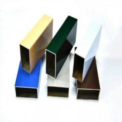
Common surface treatments include clear and color anodizing for excellent durability and metallic aesthetics, powder coating for virtually unlimited color options and heavy-duty protection, and PVDF/Kynar coatings for superior UV resistance in architectural facades. Specialty options include hard anodizing for wear surfaces achieving near tool-steel hardness, and micro-arc oxidation for ceramic-like surfaces in extreme environments. Surface treatment selection should influence early design decisions including alloy choice and wall thickness specifications.
For profile cross-sections, use DXF (Drawing Exchange Format) for universal 2D geometry compatibility or DWG for preserving layers and annotations. For 3D models, STEP format provides neutral geometry transfer between different CAD platforms. Always include fully dimensioned 2D drawings with tolerances, material specifications, Critical-to-Function dimensions highlighted, and surface finish requirements. Avoid sending only proprietary native files unless confirmed your manufacturer uses the same software version.


 خدمة الإنترنت
 0086 136 3563 2360
 sales@sxalu.com
 +86 136 3563 2360
 العربية
 English
 français
 Deutsch
 русский
 español
 português
 ไทย
ไทย Việt
Việt Українська